Warning, 7every 6 months maintenance, Every 6 months maintenance – AERCO Esteem Users Guide User Manual
Page 10: Gf-125u
7
Every 6 Months Maintenance
• Ensure the condensate drain line is
not blocked by pouring water through
the plug port on the condensate drain
assembly. The water should flow out of
the end of the drain line. If water does
not appear at the end of the drain line,
contact a qualified service technician to
inspect and clean the condensate line.
• To fill the condensate drain assembly,
if necessary, remove the plug from the
condensate assembly. Slowly pour
water into the trap assembly until water
appears at the end of the drain line.
Stop filling and replace plug.
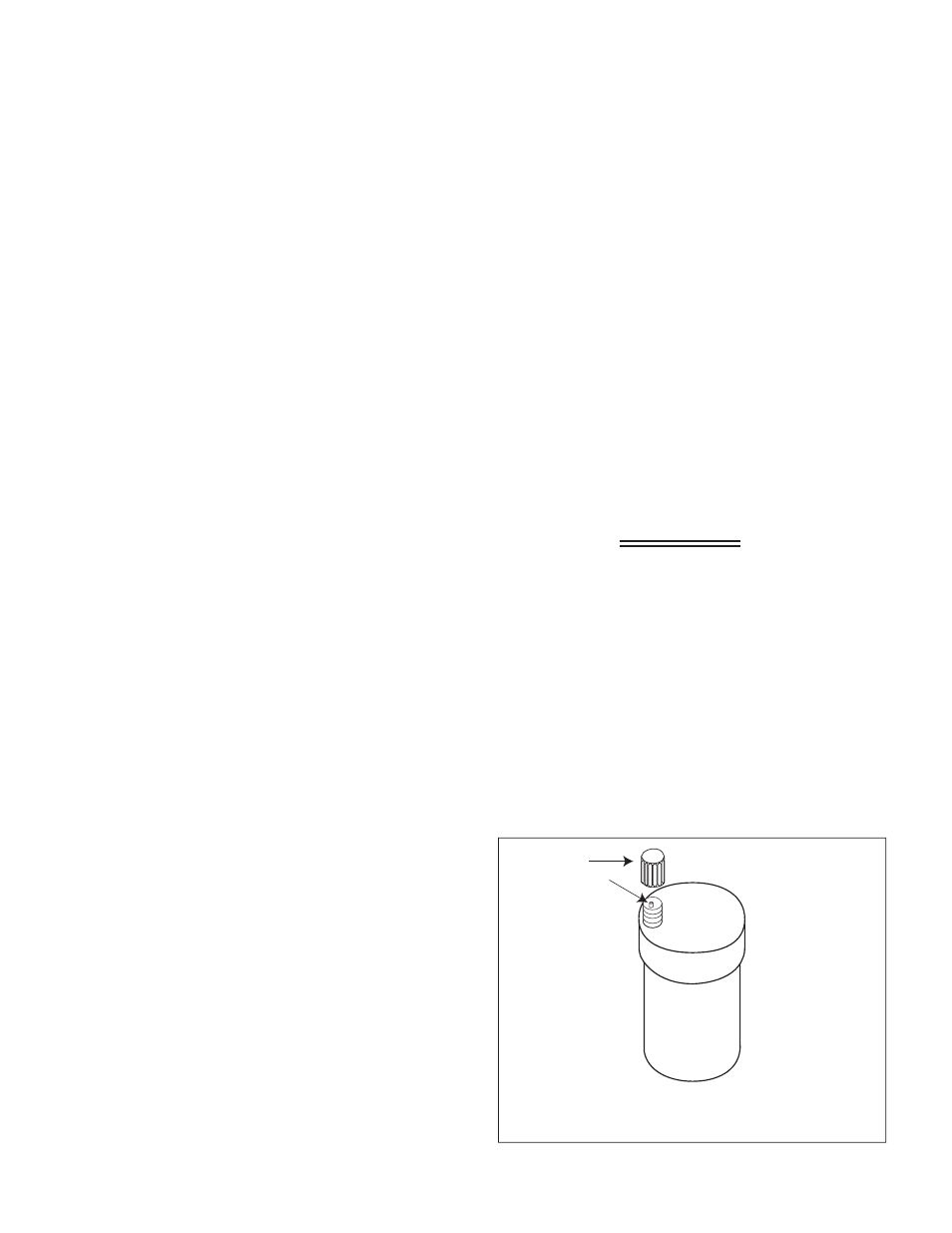
Check Automatic Air Vents (If Used)
1. Remove the cap “A” from any automatic
air vent in the system and check opera-
tion by depressing valve “B” slightly
with the tip of a screwdriver.
See Figure 2.
2. If the air vent valve appears to be work-
ing freely and not leaking, replace cap
“A”, screwing it on fully.
3. Loosen cap “A” one full turn to allow
vent to operate properly.
4. Have the air vent replaced by a quali-
fied service technician if it does not
operate correctly.
Every 6 Months Maintenance
Check Water and Gas Piping
• Remove the boiler front jacket panel
and perform a gas leak inspection per
steps 1 through 6 of the Operating
Instructions on page 7. If gas odor
or leak is detected, immediately shut
down the unit following procedures on
page 7. Call a qualified service techni-
cian.
• Visually inspect for leaks around the
internal boiler water connections and
around the heat exchanger. Visually
inspect the external system piping, cir-
culators, and system components and
fittings. Immediately call a qualified ser-
vice technician to repair any leaks.
WARNING!
H
AVE
LEAKS
FIXED
AT
ONCE
BY
A
QUALIFIED
SERVICE
TECHNICIAN
. F
AILURE
TO
COMPLY
COULD
RESULT
IN
SEVERE
PERSONAL
INJURY
,
DEATH
OR
SUBSTANTIAL
PROPERTY
DAMAGE
.
Operate Pressure Relief Valve
• Before proceeding, verify that the relief
valve outlet has been piped to a safe
place of discharge, avoiding any possi-
bility of scalding from hot water.
A
B
Figure 2: Automatic Air Vent
GF-125U