Installation – AERCO BMK 3.0 LN Nat. Gas June 2010 User Manual
Page 19
INSTALLATION
2-7
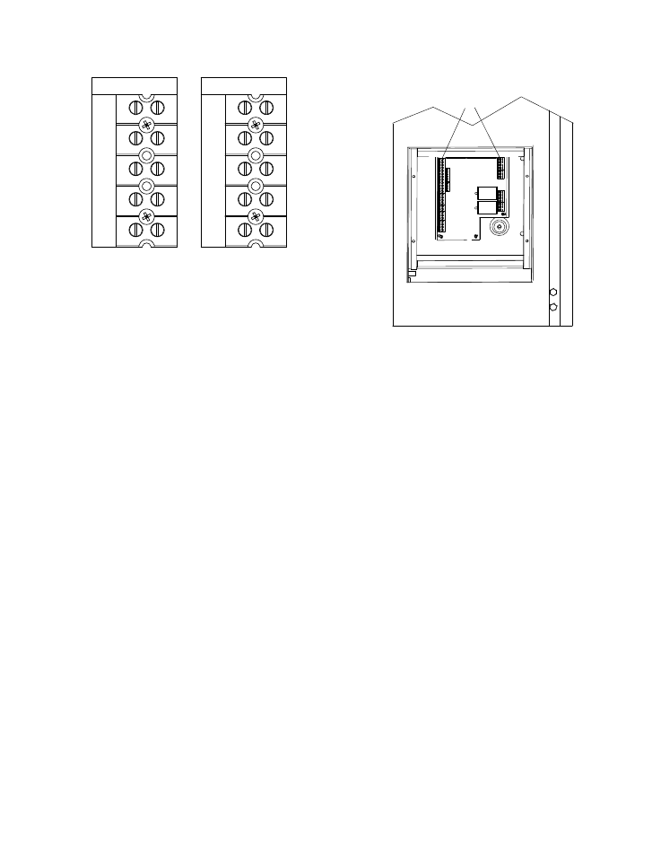
GND
NEU
L2
L3
L1
208 VAC, 3 PHASE
208 VAC, 3 Phase
GND
L2
L3
L1
460 VAC, 3 PHASE
460 VAC, 3 Phase
Figure 2-9
AC Terminal Block Configurations
2.9 MODES OF OPERATION AND FIELD
CONTROL WIRING
The Benchmark 3.0 Boiler is available in several
different modes of operation. While each unit is
factory configured and wired for its intended
mode, some additional field wiring may be
required to complete the installation. This wiring
is typically connected to the Input/Output (I/O)
Box located on the lower portion of the unit front
panel (Figure 2-10) behind the removable front
door.
To access the I/O Box terminal strips shown in
Figure 2-10, loosen the four cover screws and
remove the cover. All field wiring is installed
from the rear of the panel by routing the wires
through one of the four bushings provided.
TERMINAL
STRIPS
LOWER RIGHT CORNER
OF FRONT PANEL
Figure 2-10.
Input/Output (I/O) Box Location
Refer to the wiring diagram provided on the
cover of the I/O Box (Figure 2-11) when making
all wiring connections.
Brief descriptions of each mode of operation,
and their wiring requirements, are provided in
the following paragraphs. Additional information
concerning field wiring is provided in paragraphs
2.9.1 through 2.9.9. Refer to Chapter 5 for
detailed information on the available modes of
operation