Installation, Ab b, Figure 2-5 condensate drain connection location – AERCO BMK 3.0 LN Nat. Gas June 2010 User Manual
Page 16: 1 exhaust manifold condensate drain, 2 connecting manifold condensate drain
INSTALLATION
2-4
The procedures to install and connect both of
the condensate drains are provided in
paragraphs 2.6.1 and 2.6.2.
SHELL DRAIN
VALVE
EXHAUST
MANIFOLD
REAR VIEW
A
A
B
B
CONDENSATE
TRAP
DRAIN
CONNECTING
MANIFOLD
DRAIN
UNIT
FRAME
CONNECTING
MANIFOLD
DRAIN
VALVE
CONDENSATE
DRAIN PIPE
TO
CONDENSATE
TRAP
SHELL
VIEW “B - B”
VIEW “A - A”
UNIT
FRAME
EXHAUST
MANIFOLD
CONDENSATE
TRAP
DRAIN
HOSE
CLAMP
1" I.D.
HOSE
TO FLOOR
DRAIN
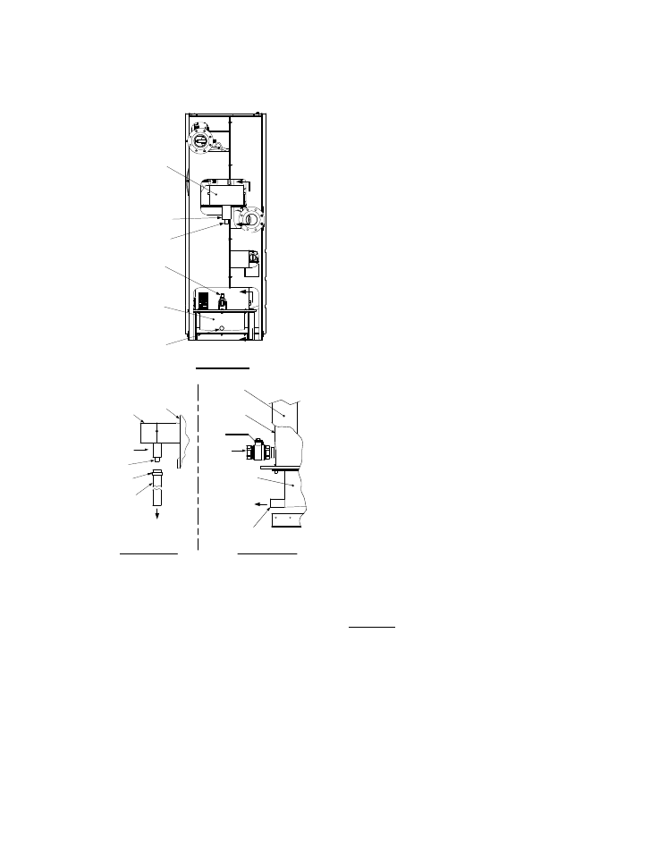
Figure 2-5
Condensate Drain Connection Location
2.6.1 Exhaust Manifold Condensate
Drain
Refer to Figure 2-5, View A – A and install as
follows:
1. Connect a length of 1 inch I.D. hose (part no.
91030) to the drain on the exhaust manifold
and secure it in place with a hose clamp.
2. Route the hose to a nearby floor drain.
2.6.2 Connecting Manifold Condensate
Drain
The connecting manifold drain pipe shown in
Figure 2-5, View B – B must be connected to a
separate condensate drain trap external to the
unit. This condensate trap (part no. 24060) is
supplied with the unit along with a trap adapter
and a 3/4” NPT x 5” long nipple. Refer to Figure
2-6 and install the trap as follows:
NOTE
The condensate trap described in the
following steps can be installed on the
floor behind the unit as shown in Figure 2-
6. Ensure that the condensate trap inlet is
level with or below the connecting
manifold drain pipe. Ensure that the outlet
hose from the trap slopes away (down)
from the trap.
1. Apply Teflon tape to the threads of the 3/4” x
5” long nipple provided with the boiler.
2. Attach the 3/4” NPT nipple between the
condensate trap inlet and the trap adaptor
(Figure 2-6).
3. Attach another 3/4” NPT nipple (not sup-
plied) to the condensate trap outlet on the
lower part of the trap.
4. Connect the condensate trap and adaptor to
the connecting manifold drain pipe. Position
the trap so it is level and then tighten the
thumb screw on the adaptor.
5. Place a suitable support under the
condensate trap to maintain the trap in the
level position.
6. Connect a length of 1” I.D. polypropylene hose
to the outlet side of the condensate trap and
route it to a nearby floor drain.
If desired, a Tee fitting may be used to connect the
two drain hoses from the exhaust manifold and the
outlet side of the of the condensate trap attached to
the connecting manifold.
If a floor drain is not available, a condensate pump
can be used to remove the condensate to drain.
The maximum condensate flow rate is 20 GPH.
The condensate drain trap, associated fittings and
drain lines must be removable for routine
maintenance.