2 manual gas shutoff valve, 3 iri gas train kit, 5 electrical supply – AERCO BMK 2.0 LN for Mass. only User Manual
Page 16: Installation
INSTALLATION
2-4
CAUTION!
Many soaps used for gas pipe leak testing
are corrosive to metals. Therefore, AERCO
recommends the use of non-corrosive
soaps for leak tests. The piping must be
rinsed thoroughly with clean water after leak
checks have been completed.
NOTE:
All gas piping must be arranged so that it
does not interfere with removal of any
cover, inhibit service or maintenance, or
prevent access between the Unit and walls,
or another unit.
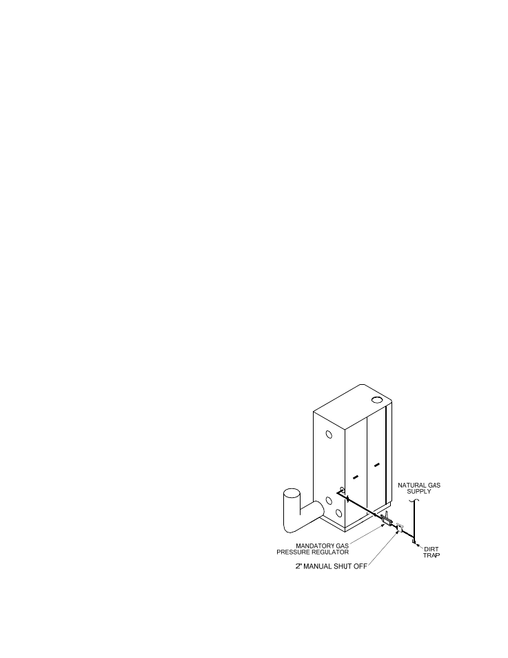
The location of the 2" inlet gas connection is
located on the rear of the unit as shown in
Figure 2.5.
All pipes should be de-burred and internally
cleared of any scale or iron chips before
installation. No flexible connectors or non-
approved gas fittings should be installed. Piping
should be supported from floor, ceiling or walls
only and must not be secured to the unit.
A suitable piping compound, approved for use
with natural gas or propane, should be used.
Any excess must be wiped off to prevent
clogging of components.
To avoid damage to the unit, when pressure
testing gas piping, isolate the unit from the gas
supply piping. At no time should there be more
than 14” W.C. to the unit. Leak test all external
piping thoroughly for leaks using a non-corrosive
soap and water solution or suitable equivalent.
The gas piping must meet all applicable codes.
2.4.1 GAS SUPPLY SPECIFICATONS
− Natural Gas:
The maximum static pressure to the unit
must be no more than 2 psi. Minimum
natural gas operating pressure is 5.3“ W.C.
for FM gas trains & 5.5“ W.C. for IRI gas
trains when the unit is firing at maximum
input (2000 cfh). For Benchmark 2.0 Low
NOx boilers configured for De-Rated
capacity, the required minimum natural gas
operating pressure is 4.0” W.C. for FM gas
trains (4.2” W.C. for IRI gas trains) at maxi-
mum input of 1,750,000 BTU/hr (1750 cfh).
A gas supply regulator must be positioned as
shown in Figure 2.5. If the gas supply pressure
will exceed 14" W.C., a lock -up style regulator is
required.
When installing the gas supply regulator(s),
union connections should be placed in the
proper locations to allow for maintenance.
The gas supply regulator must be properly
vented to outdoors. Consult the local gas utility
for exact
requirements concerning venting of
supply gas regulators.
NOTE:
The regulator must be capable or regulating
2,000,000 BTU/HR of natural gas while
maintaining 5.3” W.C. to the boiler.
CAUTION!
A lockup style regulator must be used when
gas supply pressure exceeds 14” W.C.
2.4.2 MANUAL GAS SHUTOFF VALVE
A 2” manual gas shut-off valve is furnished with
each unit. The valve should be positioned on the
inlet to the unit, as shown in Figure 2.5,
upstream of the supply regulator in a readily
accessible location.
2.4.3 IRI GAS TRAIN KIT
The IRI gas train is an optional gas train
required in some areas by code or for insurance
purposes. The IRI gas train is factory pre-piped
and wired.
Figure 2.5
Manual Shut-Off Valve Location