Initial start-up – AERCO BMK 1.5 LN May 2009 User Manual
Page 33
INITIAL START-UP
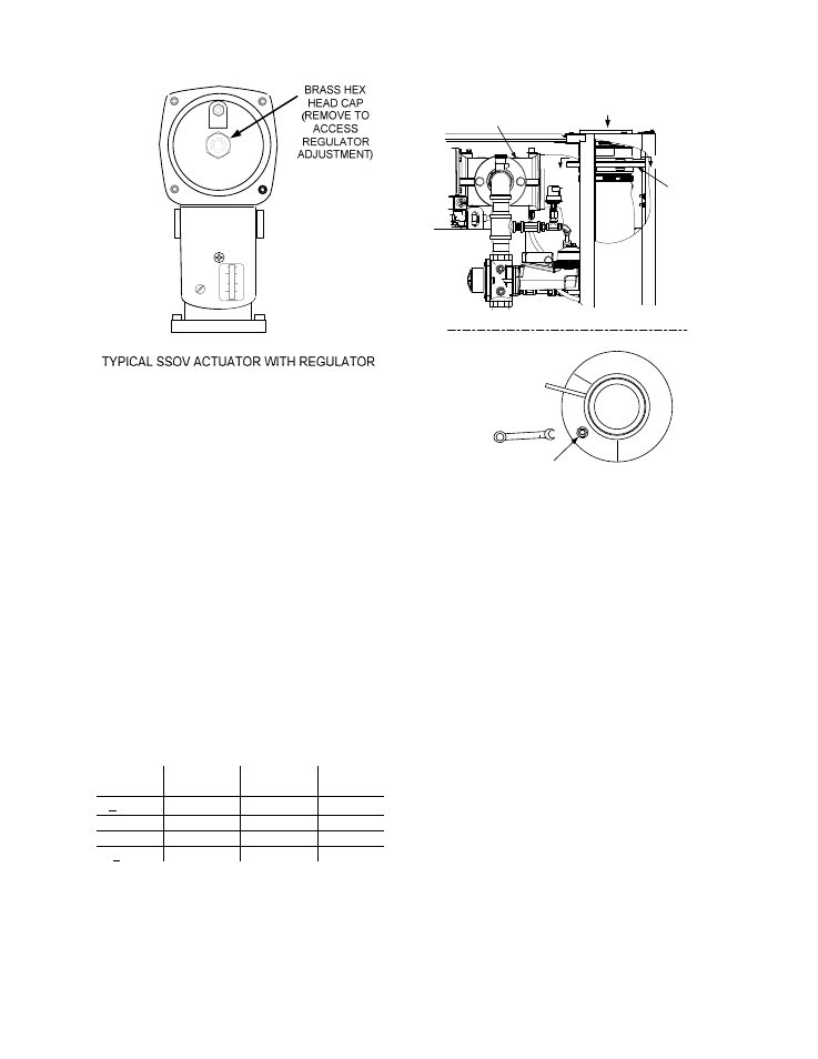
Figure 4-3
Regulator Adjustment Screw Location
11. Raise the firing rate to 100% and verify that
the gas pressure downstream of the SSOV
remains at 3” W.C. Readjust pressure if
necessary.
12. With the firing rate at 100%, insert the
combustion analyzer probe into the flue
probe opening and allow enough time for the
combustion analyzer to settle.
13. Compare the measured oxygen level to the
oxygen range for the inlet air temperature
shown in Table 4-1. Also, ensure that the
carbon monoxide (CO) and nitrogen oxide
(NOx) readings do not exceed the values
shown.
Table 4-1
Combustion Oxygen Levels for a 100%
Firing Rate
Inlet Air
Temp
Oxygen %
± 0.2
Carbon
Monoxide
NOx
>100°F
4.8 %
<100 ppm
<30 ppm
90°F
5.0 %
<100 ppm
<30 ppm
80°F
5.2 %
<100 ppm
<30 ppm
<70°F
5.3 %
<100 ppm
<30 ppm
14. If necessary, adjust the iris air damper
shown in Figure 4-4 until the oxygen level is
within the range specified in Table 4-1.
15. Once the oxygen level is within the specified
range at 100%, lower the firing rate to 80%.
USE 1/2"
WRENCH TO
INCREASE (CW)
OR DECREASE
(CCW) INLET AIR
IRIS ADJUSTMENT
VIEW A - A
AIR INLET
IRIS AIR
DAMPER
FRONT
A
A
AIR/FUEL
VALVE
Figure 4-4
Iris Air Damper Location/Adjustment
NOTE
The remaining combustion calibration
steps utilize the Variable Frequency Drive
(VFD) located behind the front door of the
unit. The VFD controls will be used to
adjust the oxygen level (%) at firing rates
of 80%, 60%, 45%, 30% and 12% as
described in the following steps. These
steps assume that the inlet air
temperature is within the range of 50°F to
100°F.
16. Locate the Variable Frequency Drive (VFD)
behind the front door of the unit. Refer to the
VFD operating controls shown in Figure 4-5.
4-3