Control panel operating procedures – AERCO BMK 1.5 LN May 2009 User Manual
Page 28
CONTROL PANEL OPERATING PROCEDURES
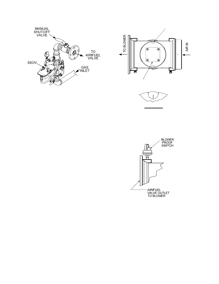
Figure 3-3.
SSOV Locations
3. With all required safety device switches
closed, a purge cycle will be initiated and the
following events will occur:
(a) The Blower relay energizes and turns
on blower.
(b) The Air/Fuel Valve rotates to the full-
open purge position and closes purge
position switch. The dial on the Air/Fuel
Valve (Figure 3-4) will read 100 to
indicate that it is full-open (100%).
(c) The FIRE RATE bargraph will show
100%.
4. Next, the blower proof switch on the Air/Fuel
Valve (Figure 3-5) closes. The display will
show Purging and indicate the elapsed time
of the purge cycle in seconds. The normal
(default) time for the purge cycle is 7
seconds.
5. Upon completion of the purge cycle, the
Control Box initiates an ignition cycle and
the following events occur:
(a) The Air/Fuel Valve rotates to the low-
fire ignition position and closes the
ignition switch. The dial on the Air/Fuel
Valve (Figure 3-6) will read between 25
and 35 to indicate that the valve is in
the low-fire position.
(b) The igniter relay is activated and
provides ignition spark.
(c) The gas Safety Shut-Off Valve (SSOV)
is energized (opened) allowing gas to
flow into the Air/Fuel Valve.
100
DETAIL “A”
DIAL
(DETAIL “A”)
STEPPER
MOTOR
Figure 3-4.
Air/Fuel Valve In Purge Position
Figure 3-5.
Blower Proof Switch
6. Up to 7 seconds will be allowed for ignition
to be detected. The igniter relay will be
turned off one second after flame is
detected.
7. After 2 seconds of continuous flame, Flame
Proven
will be displayed and the flame
strength will be indicated. After 5 seconds,
the current date and time will be displayed in
place of the flame strength.
3-8