Installation – AERCO BMK 1.5 LN May 2009 User Manual
Page 16
INSTALLATION
2-6
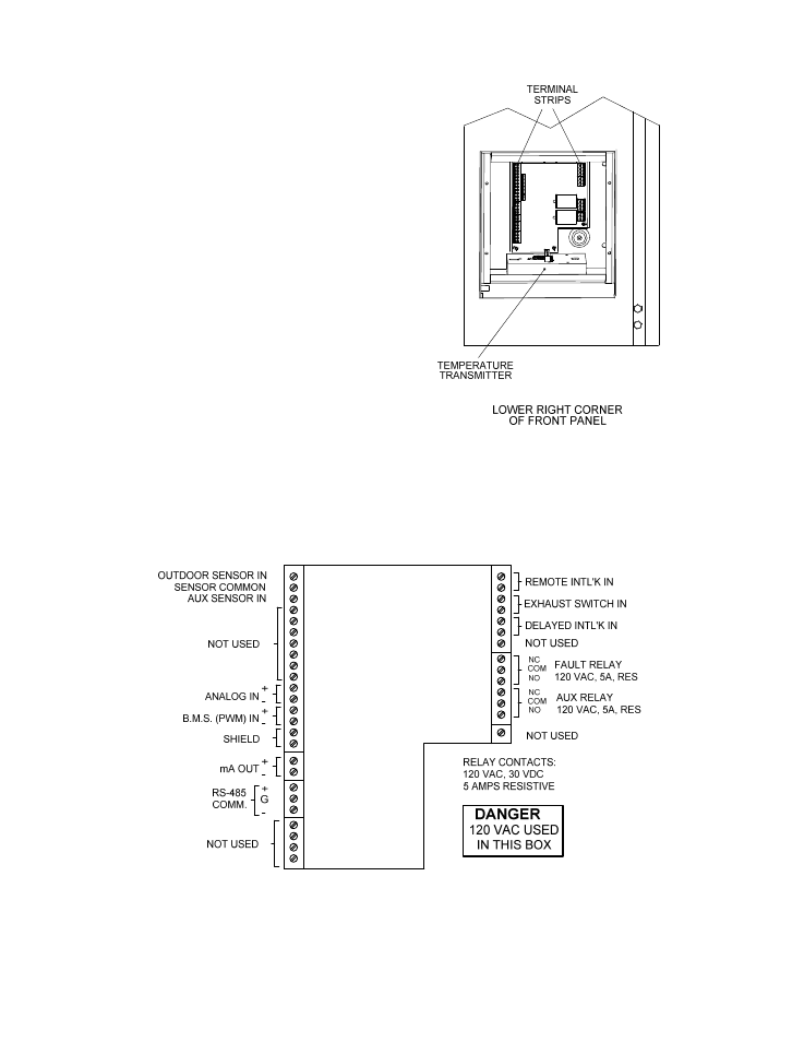
To access the I/O Box terminal strips shown in
Figure 2-10, loosen the four cover screws and
remove the cover. All field wiring is installed
from the rear of the panel by routing the wires
through one of the four bushings provided.
Refer to the wiring diagram provided on the
cover of the I/O Box (Figure 2-10) when making
all wiring connections.
In addition to the terminal strips shown in Figure
2-9, the I/O Box also contains a pre-wired
temperature transmitter which receives inlet air
temperature sensor readings and transmits this
signal to the variable frequency drive (VFD)
contained in the Benchmark 1.5 Boiler. The VFD
utilizes this input signal to adjust the rotation
speed of the blower.
Brief descriptions of each mode of operation,
and their wiring requirements, are provided in
the following paragraphs. Additional information
concerning field wiring is provided in paragraphs
2.9.1 through 2.9.9. Refer to Chapter 5 for
detailed information on the available modes of
operation.
Figure 2-9.
Input/Output (I/O) Box Location
Figure 2-10. I/O Box Terminal Strip