Installation – AERCO BMK 1.5 LN June 2010 User Manual
Page 14
INSTALLATION
2-2
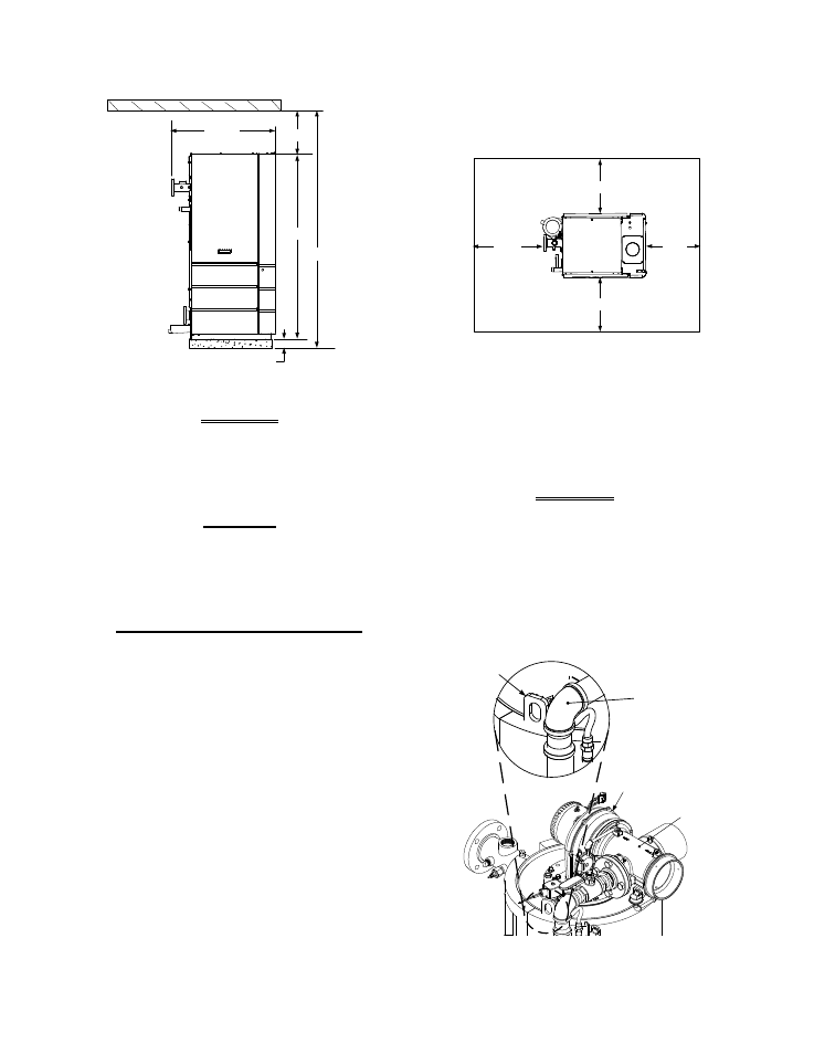
24"
4" HIGH PAD
REAR
FRONT
44.5"
18"
101"
79"
30"
24"
24"
Figure 2-1 Benchmark 1.5 Boiler Clearances
WARNING
KEEP THE UNIT AREA CLEAR AND
FREE FROM ALL COMBUSTIBLE
MATERIALS AND FLAMMABLE
VAPORS OR LIQUIDS
.
CAUTION
While packaged in the shipping
container, the boiler must be moved
by pallet jack or forklift from the
FRONT ONLY.
FOR MASSACHUSSETTS ONLY:
For Massachusetts installations, the
boiler must be installed by a plumber
or gas fitter who is licensed within the
Commonwealth of Massachusetts. In
addition, the installation must comply
with all requirements specified in
Chapter 1 (Safety Precautions), pages
1-2 & 1-3.
2.4.2 Setting the Unit
The unit must be installed on a 4 inch to 6 inch
housekeeping pad to ensure proper condensate
drainage. If anchoring the unit, refer to the
dimensional drawings in Appendix F for anchor
locations. Two lifting tabs are provided at the top
of the heat exchanger. Figure 2-2 shows the
location of the tab on the top-left side. The
second tab is located on the top-right side of the
heat exchanger. USE THESE TWO TABS TO
LIFT AND MOVE THE UNIT. Remove the top
panel from the unit to provide access to the
lifting tabs. Remove the four (4) lag screws
securing the unit to the shipping skid. Lift the
unit off the shipping skid and position it on the 4
inch to 6 inch housekeeping concrete pad
(required) in the desired location.
WARNING
WHEN LIFTING OR MOVING THE
BOILER:
• DO NOT MANIPULATE THE BOILER
USING THE GAS TRAIN OR BLOWER
• WHEN USING THE LIFTING TABS,
ENSURE THERE IS NO LOAD
PLACED ON THE GAS TRAIN OR
BLOWER
AIR/FUEL
VALVE
BLOWER
LIFTING TAB
(2 PLACES)
PART OF
GAS TRAIN
DO NOT
LIFT HERE
Figure 2-2
Partial Top View Showing Lifting Tab
Location