Dampertech_2010 63, Startup and checkout – AERCO Belimo AF120-S US Actuator User Manual
Page 9
800-543-9038 USA
866-805-7089 CANADA
203-791-8396 LATIN AMERICA
63
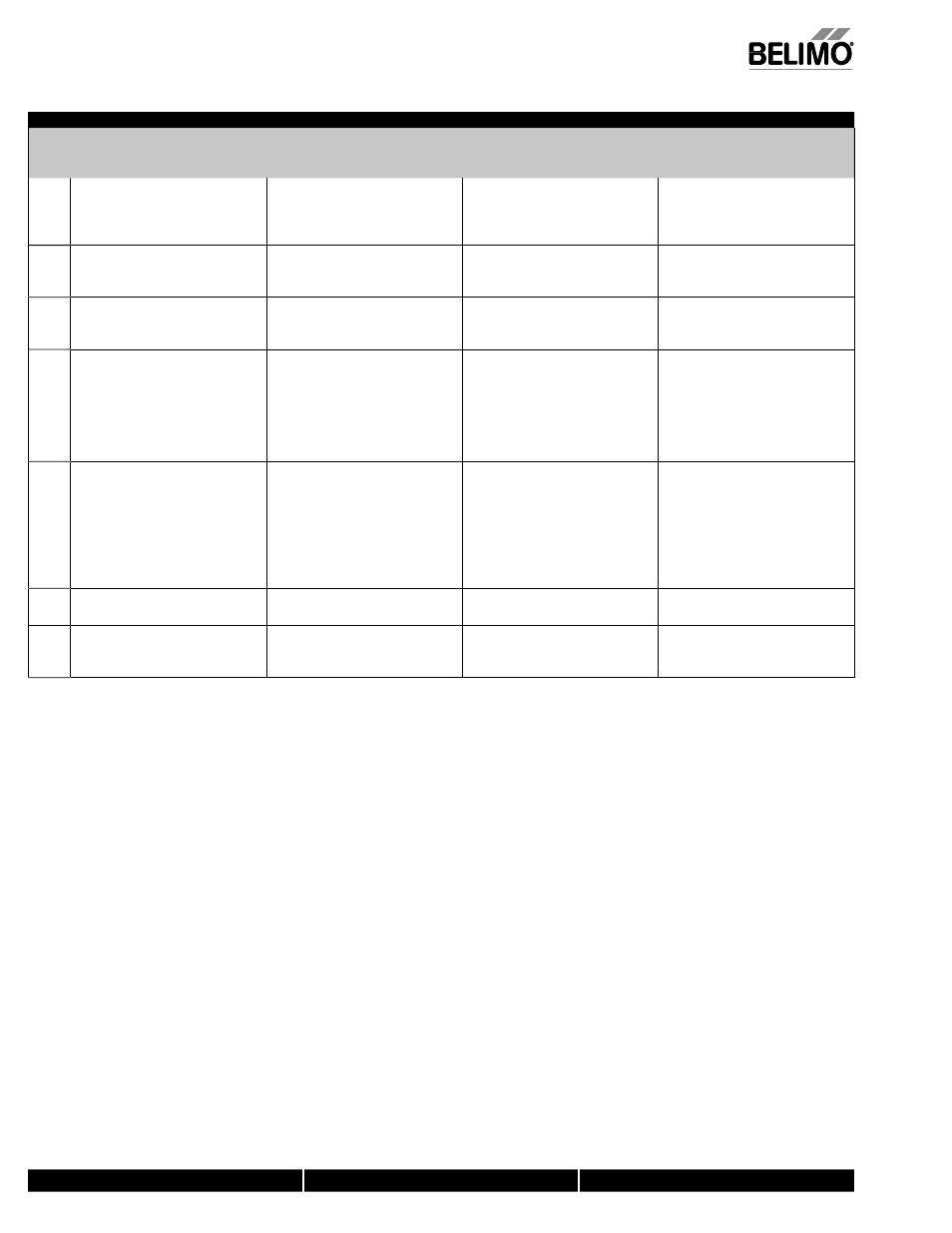
AF24-SR US Electrical Check-out Procedure
STEP
Procedure
Expected Response
Gives Expected Response
Go To Step…
Does Not Give
Expected Response
Go To Step…
1.
Control signal is applied to actuator.
Actuator will move to its “Control
Signal” position.
Actuator operates properly Step 7.
No response at all Step 2.
Operation is reversed Step 3.
Does not drive toward "Control Signal
Position" Step 4.
2.
Check power wiring.
Correct any problems.
See Note 1.
Power supply rating should be the total
power requirement of the actuator(s).
Minimum voltage of 19.2 VAC or 21.6 VDC.
Power wiring corrected, actuator
begins to drive Step 1.
Power wiring corrected, actuator still
does not drive Step 4.
3.
Turn reversing switch to the correct
position. Make sure the switch is
turned all the way left or right.
Actuator will move to its “Control
Signal” position.
Actuator operates properly Step 7.
Does not drive toward “Control Signal
Position” Step 4.
4.
Make sure the control signal positive
(+) is connected to Wire No. 3 and
control signal negative (-) is connected
to wire No. 1. Most control problems
are caused by reversing these two
wires. Verify that the reversing switch
is all the way CCW or CW.
Drives to “Control Signal” position.
Actuator operates properly Step 7.
Step 5.
5.
Check input signal with a digital volt
meter (DVM). Make sure the input
is within the range of the actuator. For
AF24-SR US this is 2 to 10 VDC or 4 to
20 mA.
NOTE: The input signal must be
above the 2 VDC or 4 mA to have
the actuator move.
Input voltage or current should be ±1%
of what controller's adjustment or
programming
indicate.
Controller output (actuator input)
is correct. Input Polarity Correct
Step 6.
Reprogram, adjust repair or replace
controller as needed Step 1.
7.
Check damper torque requirement.
Torque requirement is actuator’s
minimum torque.
Defective Actuator.
Replace Actuator - See Note 2.
Recalculate actuator requirement and
correct installation.
8.
Actuator works properly. Test
controller by following controller
manufacturer's instructions.
NOTE 1
Check that the transformer(s) are sized properly.
• If a common transformer is used, make sure that polarity is observed on the secondary. This means connect all No. 1 wires to one leg of the transformer and all
No. 2 wires to the other leg of the transformer.
• If multiple transformers are used with one control signal, make sure all No. 1 wires are tied together and tied to control signal negative (-).
• Controllers and actuators must have separate 24 VAC/VDC power sources.
NOTE 2
If failure occurs within 5 years from original installation date, notify Belimo and give details of the application.
Startup and Checkout
Instructions For AF24-SR US
M40024 - 05/10 - Subject to change.
© Belimo
Aircontrols (USA),
Inc.