AERCO AERClean User Manual
Page 8
Page 8
Benchmark Low NOx Series
AERClean Filtration System Instructions
Doc#
TID-0001-0A
Created: 10/13/2010
Revised: 11/11/2010
Owner: BS-Manager_V.D.
DOC#: TID-0001-0A
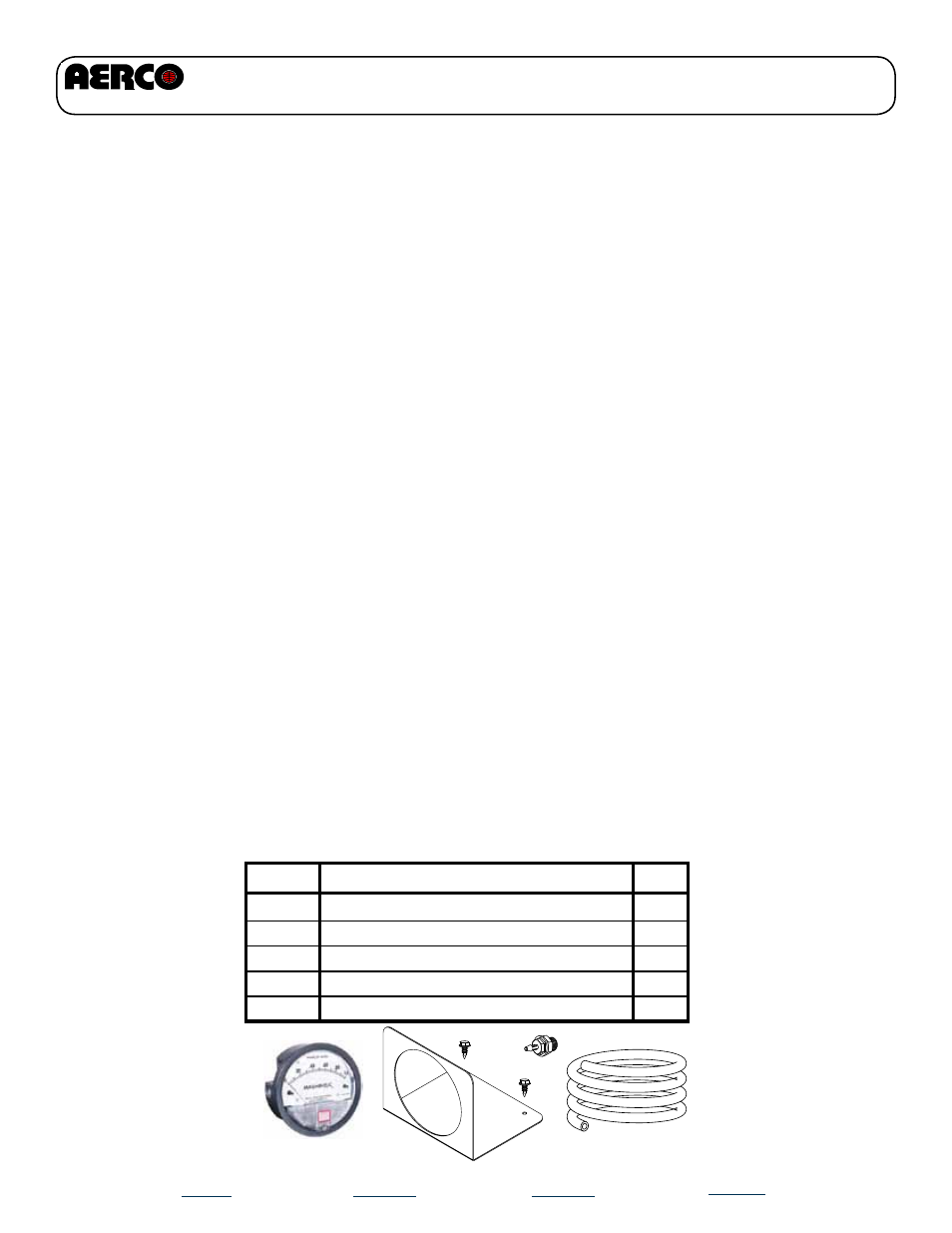
P/N 58032 - Dwyer Magnehelic Differential Pressure Gauge Kit
P/N
67005
91083
97053
33125
Description
Dwyer Magnehelic Diff. Press. Gauge
5/16 O.D., 3/16 I.D. PVC Tubing
3/16” Barbed Fitting
Dwyer Magnehelic mounting Bracket
Qty
1
1
1
1
54010
#10-16 sheet metal screw, 1/2 Long
2
INTRODUCTION
The Magnehelic® gauge is a high accuracy pressure gauge measuring low air or non-corrosive
gas pressures--either positive, negative (vacuum) or differential. The design resists shock, vibra-
tion and over-pressures. It is the industry standard to measure fan and blower pressures, filter resis-
tance, air velocity, furnace draft, pressure drop across orifice plates, liquid levels with bubbler systems
and pressures in fluid amplifier or fluidic systems. It also checks gas-air ratio controls and automatic
valves, and monitors blood and respiratory pressures in medical care equipment.
INSTALLATION
Select a location free from excessive vibration and where the ambient temperature will not exceed
140°F (60°C). Also, avoid direct sunlight which accelerates discoloration of the clear plastic cover.
Sensing lines may be run any necessary distance. Long tubing lengths will not affect accuracy
but will increase response time slightly. Do not restrict lines. If pulsating pressures or vibration
cause excessive pointer oscillation, consult the factory for ways to provide additional damping.
All standard Magnehelic® Differential Pressure Gauges are calibrated with the diaphragm vertical
and should be used in that position for maximum accuracy. If gauges are to be used in other than
vertical position, this should be specified on the order. Many higher range gauges will perform
within tolerance in other positions with only re-zeroing. Low range models of 0.5” w.c. plus 0.25”
w.c. and metric equivalents must be used in the vertical position only.
SURFACE MOUNTING
Locate mounting holes, 120° apart on a 4-1/8” dia. circle. Use No. 6-32 machine screws of appro-
priate length. Provide a 4-9/16” dia. (116 mm) opening in panel. Provide a 4- 3/4” dia. (120 mm)
opening for MP and HP models. Insert gage and secure in place with No. 6-32 machine screws of
appropriate length, with adapters, firmly secured in place.
TO ZERO GAGE AFTER INSTALLATION
Set the indicating pointer exactly on the zero mark, using the external zero adjust screw on the
cover at the bottom. Note that the zero check or adjustment can only be made with the high and
low pressure taps both open to atmosphere.
OPERATION
Negative Pressure: Connect tubing from source of vacuum or negative pressure to either of the
two low pressure ports. Plug the port not used. Vent one or both high pressure ports to atmo-
sphere.