AERCO AERClean User Manual
Page 10
Page 10
Benchmark Low NOx Series
AERClean Filtration System Instructions
Doc#
TID-0001-0A
Created: 10/13/2010
Revised: 11/11/2010
Owner: BS-Manager_V.D.
DOC#: TID-0001-0A
ELECTRICAL CONNECTION (Cont.)
Protect the feed line (to pole 3) with a fuse, either in control system or along the line as follows:
• 1) Max. 1.5 A / 250 VAC, if you are loading the contact with resistive load.
• 2) Max 0.4 A / 250 VAC, if you are loading the contact with inductive load (such as relay).
• 3) Max. 0.1 A / 250 VDC, if you are using the pressure switch in the weak current version
with gold-plated contacts.
The connections are intended for crimp-type sockets, 0.25 in (6.3 mm):
• Make sure the cable lugs fit properly onto the connections.
• When using rigid copper wire, use cable lugs with mounted screw terminals.
• For flex, it is necessary to crimp on strand end sleeves – and then also screw strands on.
CAUTION:
Ensure there is no voltage on the electrical connections before applying any settings to the
pressure switch.
SETTING THE PRESSURE RANGE
Use the setting screw to set the rotary adjustment to 0.5” w.c.. Note that the indication on the set-
ting screw is only correct for the vertical mounting position. If mounted In the horizontal position,
the switching values are approximately 0.08 in w.c. (20 Pa) higher as indicated on the scale.
CLOSING THE SWITCH
• Insert the screw cable connection into the recess provided for this purpose on the housing.
• Then place the housing cover in position, and screw it down evenly on to the pressure
switch.
TESTING THE SETTING
Partially block the air inlet to test. Insert a “T” into the hose and hook up a nanometer to check for
a trip point of 0.5” w.c.
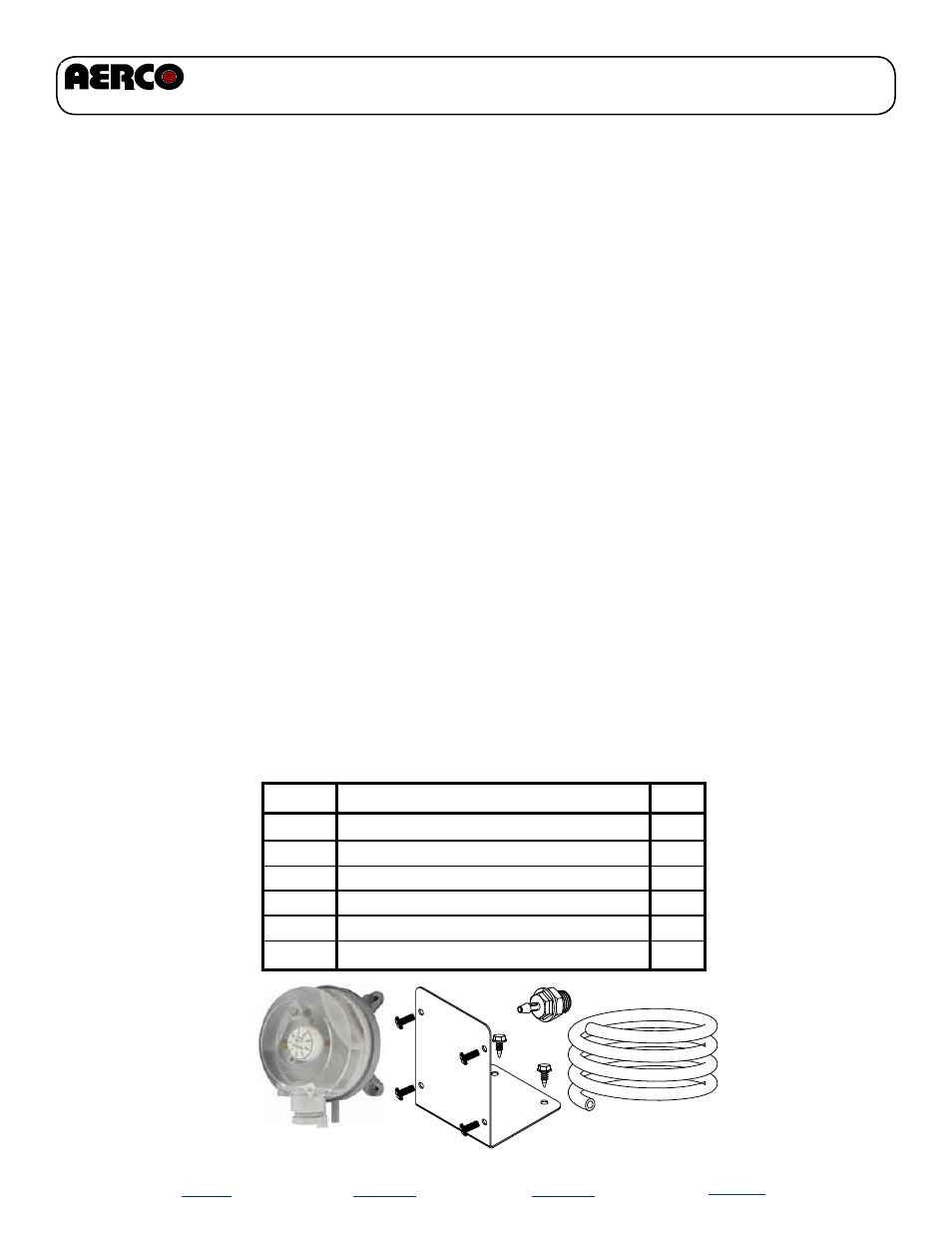
P/N
60016
54083
91083
97053
33125
Description
Dwyer Differential Pressure Switch
#6-32 screw, 5/16 Long
5/16 O.D., 3/16 I.D. PVC Tubing
3/16” Barbed Fitting
Dwyer Switch Mounting Bracket
Qty
1
4
1
1
1
54010
#10-16 sheet metal screw, 1/2 Long
2
Kit P/N 58034 - Dwyer Adjustable Differential Pressure Switch