Typical 6 - load point assembly installation, Level requirements, Stiffness – Hardy HI LPRE05 Shear Beams User Manual
Page 17: Level requirements stiffness
OPERATION AND INSTALLATION MANUAL
Page 11
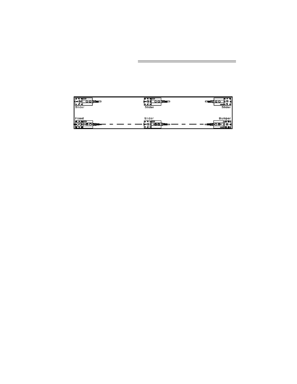
Typical 6 - Load
Point Assembly
Installation
FIG. 14: SIX LOAD CELLS POSITIONED IN A
RECTANGULAR CONFIGURATION
NOTE:
In case there is doubt concerning load point assembly
installation, contact your local Hardy Process Solu-
tions dealer, Application Engineering Department, or
Customer Support Department for assistance.
You can orient the load point assemblies to meet your
system installation requirements. All load point
assemblies can be rotated 360
o
in 90
o
increments. The
examples above are recommendations only.
Level Requirements
For scales that must meet NIST Class 3 (OIML Class
3) specifications:
1.
The base plate support surfaces must be
within 0.2 degrees (0.4mm/100mm)
2.
The top plate support surfaces in the load
carrier must be within 0.5 degrees (0.9mm/
100mm)
For scales with accuracy requirements => 0.1%
1.
The base plate support surfaces must be
within 0.4 degrees (0.08mm/100mm)
2.
Top plate support surfaces in the load carrier
must be within 1 degree (1.8mm/100mm)
Stiffness
Load variations and external forces can cause support
surface level variations.