Hardy Advantage Weigh Modules LPB User Manual
Page 22
HI LPB SERIES LOAD POINT ASSEMBLY
Page 16
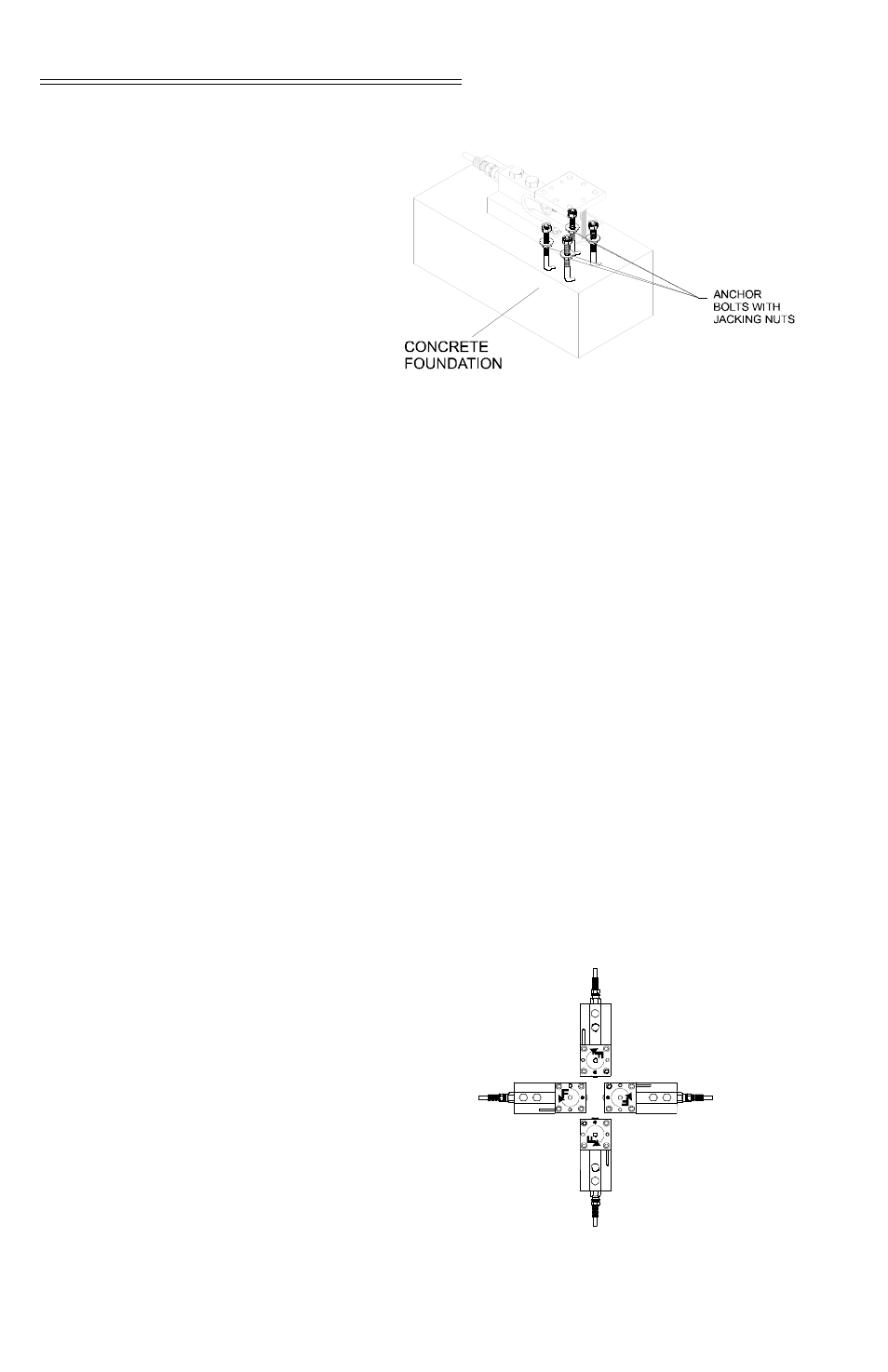
FIG. 18: INSTALLING THE FOUR ANCHOR
BOLTS FOR THE BASE PLATE
Step 10.
Install the correct size Jacking Nuts onto
the Anchor Bolts so there is about 1/2 inch
between the concrete foundation and the
jacking nuts. Don’t worry about level at
this point, you will level everything after
the Load Point Assembly/base plate is
Installed.
Step 11.
Install four flat washers on each anchor
bolt above the jacking nuts.
Step 12.
Slide the load point assembly/base plate
onto the anchor bolts. You can install the
load point assemblies in one of four orien-
tations. (See Fig. 19) Notice we used the
Free Sliding Load Point Assembly for this
illustration but you can do the same with
any of the load point assembly types.
FIG. 19: LOAD POINT ORIENTATION