Step 5 — wire low voltage connections – Carrier AQUAZONE 50PEC09-18 User Manual
Page 30
30
Table 2 — Electrical Data — 50PEC Units
LEGEND
Step 5 — Wire Low Voltage Connections
WATER FREEZE PROTECTION — The Aquazone™ con-
trol allows the field selection of source fluid freeze protection
points through jumpers. The factory setting of jumper JW3
(FP1) is set for water at 30 F. In earth loop applications, jumper
JW3 should be clipped to change the setting to 10 F when
using antifreeze in colder earth loop applications. See Fig. 30.
ACCESSORY CONNECTIONS — Terminal labeled A on
the control is provided to control accessory devices such as
water valves, electronic air cleaners, humidifiers, etc. This
signal operates with the compressor terminal. See Fig. 31.
Refer to the specific unit wiring schematic for details.
NOTE: The A terminal should only be used with 24-v signals
— not line voltage signals.
WATER SOLENOID VALVES — An external solenoid
valve(s) should be used on ground water installations to shut
off flow to the unit when the compressor is not operating. A
slow closing valve may be required to help reduce water
hammer. Figure 31 shows typical wiring for a 24-vac external
solenoid valve. Figures 32 and 33 illustrate typical slow closing
water control valve wiring for Taco 500 Series and Taco ESP
Series valves. Slow closing valves take approximately 60 sec.
to open (very little water will flow before 45 sec.). Once fully
open, an end switch allows the compressor to be energized
(only on valves with end switches). Only relay or triac based
electronic thermostats should be used with slow closing valves.
When wired as shown, the slow closing valve will operate
properly with the following notations:
1. The valve will remain open during a unit lockout.
2. The valve will draw approximately 25 to 35 VA through
the “Y” signal of the thermostat.
50PEC
UNIT SIZE
VOLTAGE
CODE
V-PH-Hz
MIN/MAX
VOLTAGE
COMPRESSOR
FAN MOTOR
FLA
TOTAL UNIT
FLA
MIN CIRCUIT
AMPS
MAX
FUSE/HACR
QTY
RLA
LRA
09
1
115-1-60
104/126
1
8.1
46.5
0.6
8.6
10.7
15
3
208/230-1-60
197/254
1
4.5
23.0
0.4
4.9
6.0
15
4
265-1-60
239/292
1
3.1
24.0
0.4
3.5
4.3
15
12
1
115-1-60
104/126
1
10.6
55.8
1.0
11.6
14.3
25
3
208/230-1-60
197/254
1
5.2
24.0
0.6
5.8
7.1
15
4
265-1-60
239/292
1
4.2
25.0
0.4
4.6
5.7
15
15
3
208/230-1-60
197/254
1
6.1
30.0
0.8
6.9
8.4
15
4
265-1-60
239/292
1
4.7
28.5
0.6
5.3
6.5
15
18
3
208/230-1-60
197/254
1
6.8
38.0
0.7
7.5
9.2
15
4
265-1-60
239/292
1
6.2
29.0
0.6
6.8
8.4
15
FLA
— Full Load Amps
HACR — Heating, Air Conditioning and Refrigeration
LRA
— Locked Rotor Amps
RLA
— Rated Load Amps
IMPORTANT: Connecting a water solenoid valve can
overheat the anticipators of electromechanical thermo-
stats. Only use relay based electronic thermostats.
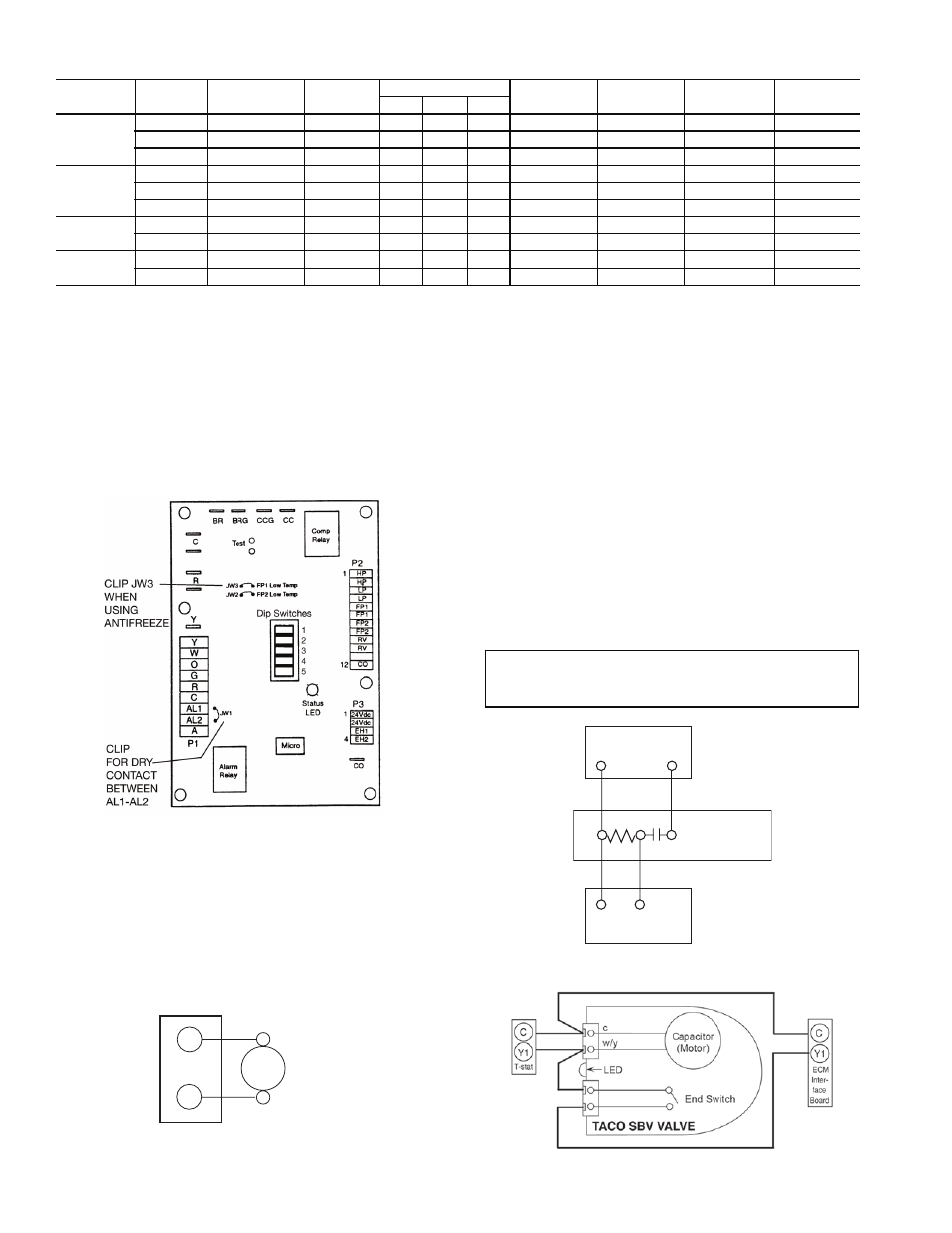
AQUAZONE CONTROL (Complete C Control Shown)
Fig. 30 — Typical Aquazone Control Board
Jumper Locations
a50-7467tf
Typical
Water
Valve
C
A
24 VAC
Terminal Strip
Fig. 31 — Typical Aquazone Accessory Wiring
Fig. 32 — AMV Valve Wiring
C
C
THERMOSTAT
1
Y
1
2
3
1
Y
AMV
TACO VALVE
HEATER SWITCH
a50-8441
Fig. 33 — Taco SBV Valve Wiring
a50-8442