Table 2-2 – CyberData VoIP Intercom User Manual
Page 17
Installing the VoIP Intercom
Intercom Setup
Operations Guide
930181B
CyberData Corporation
9
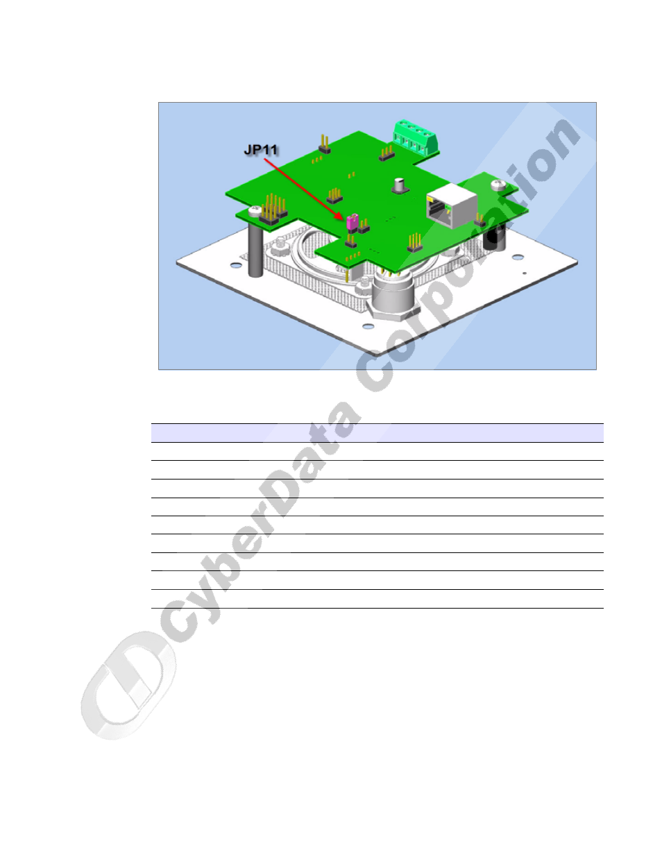
Figure 2-7. JP11—RTFM Switch Jumper
See
for the connector settings.
Table 2-2. Connector Settings
Jumper
Setting
J1
Network Connection
J4
J-Tag (Factory only)
J7
Terminal Block (see the diagram above, Figure ??)
JP2
Call-Button/LED interface
JP4
Reset (Factory only)
JP5
Microphone Interface
JP6
Speaker Interface
JP8
Console (Factory only)
JP11
RTFM (describe in text)