Cub Cadet U-Channel Beam Style User Manual
Page 19
Hydrualic Diagnosis
15
The Cylinder See Figure 3.7.
• Both ports of the cylinder are connected to the
control valve.
• When pressure is applied to the port at the base of
the cylinder (through the flexible high-pressure
hose), the ram extends.
• When pressure is applied to the shaft end of the
cylinder (through the trunnion), the ram retracts.
• When pressure is applied to one port, fluid from
the other port is forced back to the control valve by
the movement of the piston in the cylinder bore.
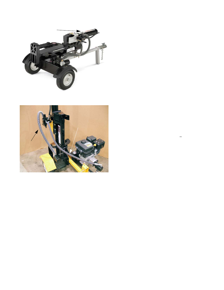
The Hoses:
The high pressure hoses:
• High-pressure hoses connect the pump to the
control valve and the control valve to the base of
the cylinder.
• High pressure means 3,400 PSI (+ 100) working
pressure.
The low pressure hoses:
• Low pressure hoses connect the tank to the pump
and the control valve to the tank.
• Hoses must not collapse under the suction pres-
sure to the pump.
• Low pressure hoses are fastened with hose
clamps.
NOTE: The low pressure hose that supplies the pump carries fluid under vacuum. If it leaks, it will draw-in air,
but may leak very little fluid out. This entrapped air will create cavitation in the pump. Poor pump perfor-
mance accompanied by whining or growling noises can indicate a leaky suction-side hose.
NOTE: The pressure of the fluid in the low pressure hose that runs from the control valve to the tank can be
approximately 300 PSI.
Figure 3.7
Cylinder
Figure 3.8
High pressure hose
Low pressure
hose