Cub Cadet U-Channel Beam Style User Manual
Page 10
2010 Log Splitters
6
NOTE: If the engine is not being replaced, skip to
step 10.
7.
Remove the set screw in the engine coupling using
a 1/8” hex key. See Figure 2.3.
NOTE: When installing the engine coupling, apply a
small amount of releasable thread locking
compound such as Loctite® 242 (blue) to
the set screw and tighten it to a torque of 78
in lbs (9 Nm)
8.
Remove the engine coupling and key.
NOTE: If the pump shows any signs of an impact,
check the coupling support bracket. If the
bracket is bent, replace the bracket and the
bolts. A bent bracket or bolts may put a side
load on the pump input shaft, damaging the
bearings.
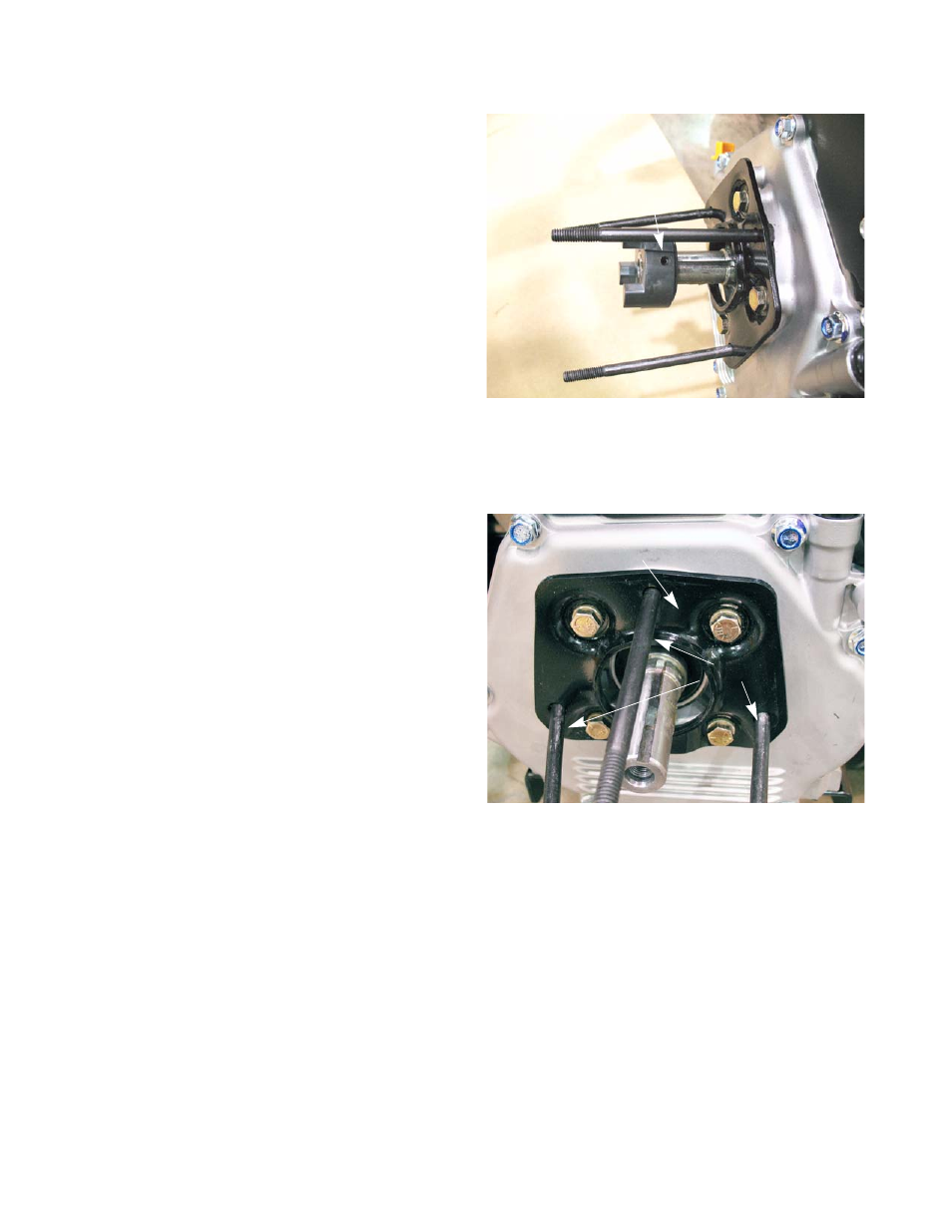
9.
Remove the front coupling support bracket using a
1/2” wrench. See Figure 2.4.
10.
Install the engine by following the previous steps in
reverse order.
NOTE: The three long bolts must be in the front
coupling support bracket before it is
attached to the engine.
NOTE: Tighten the engine mounting screws to a
torque of 325 - 450 in lbs (37 - 51 Nm).
11.
Adjust the engine coupler gap by following the steps
described in the engine coupler gap section of this
chapter.
12.
Test run the log splitter before returning it to service.
Figure 2.3
Set screw
Figure 2.4
Front coupling support bracket
Long bolts