Checkline DT-5TS User Manual
Page 8
8
Mode -01- (RPM or Rate Measurement) continued
Set the parameters in mode -01- as follows:
1.
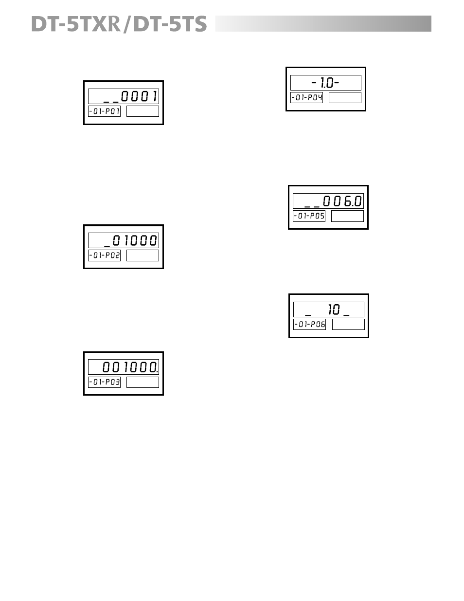
Press the PAR button; the display will indicate:
The “-01- P01” on secondary display A indicates that
the meter is in the RPM mode (-01-) and parameter 1
is showing on the primary display (1 ppr [factory
setting]).
2.
Using the NUMERIC buttons, enter the number of
pulses per revolution produced by the sensor being
used (1-9999). For example, if a rotary pulse
generator has an output of 60 ppr, then 6 0 would
have to be entered.
3.
Press the PAR button; the display will reflect:
The secondary display A reflects that the meter is
still in mode -01-, but parameter 2 is showing on the
primary display (1000 RPM [factory setting]).
4.
Using the NUMERIC buttons, enter the number of
RPM that must be monitored (up to 99999). For
example, if the motor to be monitored has a speed
of 1,750 RPM, then 1 7 5 0 would have to be entered.
5.
Press the PAR button; the display will show:
As the secondary display indicates, parameter 3 is
reflected on the primary display (1000 [factory
setting]).
6.
Use the NUMERIC buttons to enter the value of the
display as it relates to the already programmed RPM
setting. For example: if the desired display reading
is feet per minute and the belt that is being measured
is moving at a rate of 55.5 f/min, then 5 5 5 would
have to be entered and the negative/decimal point
button pressed once. If the desired reading is RPM,
then the same 1 7 5 0 would have to be entered.
7.
Press the PAR button; the display will reflect:
Parameter 4 is now showing on the primary display
(1.0 second [factory setting]).
8.
Use any of the lower buttons to scroll through the
update times (see table under “Setting Mode
Parameters” on page 7) until the desired reading is
displayed.
9.
Press the PAR button, the display will indicate:
The primary display is now reflecting parameter 5
(6 sec [factory setting]).
10. Press the NUMERIC buttons to enter the value in
seconds that the display should hold the final reading
after the input signal ceases.
11. Press the PAR button; the display will reflect:
Parameter 6 is showing on the primary display (10
kHz [factory setting]).
12. Refer to the “Connection of Sensors” chart under
the “Set-Up” section for the proper filter for the
sensor being used. Press any of the lower buttons
to scroll through the input filters (see table under
“Setting Mode Parameters” on page 7) until the
desired reading is showing.
13. Press the SET button to store the parameter settings
and exit.
NOTE
: Please see page 13 for an example of MODE -01-
operation.