How to operate” teaching feature – Checkline DT-5TS User Manual
Page 10
10
Mode -03- (Process Time Measurement)
The following parameters must be set in mode -03- so that the DT-5TXR/DT-5TS will display the correct readings:
Instructions for setting parameters in mode -03- are as
follows:
1.
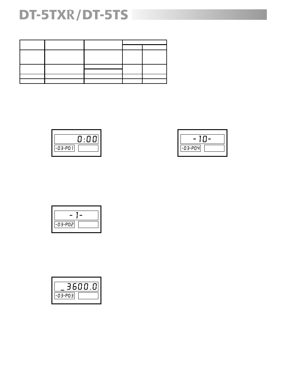
Press the PAR button; the display will indicate:
The secondary display A shows that the meter is in
mode -03-, and parameter 1 is showing that the
primary display will count in hundredths of a second
(000.00).
2.
Use any of the lower buttons to toggle between
the meter reading in seconds or reading in hours,
minutes, and seconds (see table above ).
3.
Press the PAR button; the display will indicate:
Parameter 2 is showing on the primary display
(1 [factory setting]).
4.
The input signal edge can be triggered by the leading
edge (1) or trailing edge (0). Press any of the lower
buttons to toggle between these two settings (see
table above).
5.
Press the PAR button; the display will reflect:
“How to Operate” Teaching Feature
NOTE
: This feature can only be used in mode -01-.
With the DT-5TXR/DT-5TS it is possible to monitor the speed
of a motor when the number of pulses that the sensor is
generating is unknown. The RPM can be programmed
into the meter if it is already known or discovered by
using a handheld tachometer (Shimpo models DT-105A
or DT-107A for contact measurement; DT-205LR or DT-207LR
for non-contact measurement). The meter will then use
this number to set parameters 1 and 2.
Set the teaching feature as follows:
1.
Determine the output RPM.
2.
Confirm that the meter is receiving a signal from the
sensor (the SIG indicator will be illuminated).
3.
Press the TEA button (the TEA indicator will be
illuminated).
4.
Use the NUMERIC buttons to enter the known RPM.
5.
Press the SET button to save the setting.
The parameters for mode -03- are completely different for those of mode -01- and mode -02-.
The primary display is now showing parameter 3
(3600 sec [factory setting]).
6.
Use the NUMERIC buttons to enter the amount of
time in seconds that the display needs to hold the
measured process.
7.
Press the PAR button; the display will indicate:
Parameter 4 is showing on the primary display (10kHz
[factory setting]).
8.
Refer to the “Connection of Sensors” chart under
the “Set-Up” section for the proper filter for the
sensor being used. Press any of the lower buttons
to scroll through the input filters (see table above)
until the desired reading is showing.
9.
Press the SET key to save these parameter settings
and exit.
NOTE
: Please see page 14 for an example of MODE -03-.
DISPLAY
MEANING
Hours, minutes, seconds
00:00:00
or
or
Hundreds of a second
0:00
0 = Trailing edge
1 = Leading edge
3
Auto zero time
0.1 – 3,600 seconds
_
3600.0
3600 seconds
4
Filter
10, 0.02 kHz
_
10 _
10 kHz
FACTORY SETTING
RANGE
SETTING
PARAMETER
2
d
n
o
c
e
s
0
0
1
/
1
1
0:00
_
1 _
Leading edge
Input signal edge