Checkline TI-007DL User Manual
Page 5
– 5 –
The Transducer
The transducer is the “business end” of the TI-007DL. It transmits and receives ultra-
sonic sound waves that the TI-007DL uses to calculate the thickness of the material
being measured. The transducer connects to the TI-007DL via the attached cable, and
one coaxial connector.
The transducer must be used correctly in order for the TI-007DL to produce accurate,
reliable measurements. Below is a short description of the transducer, followed by
instructions for its use.
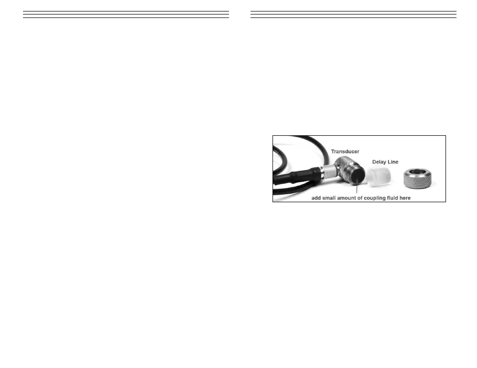
The photo below shows a typical single element delay line transducer. This delay line
is fastened to the transducer with a retainer ring. A drop of couplant is applied between
the delay line and transducer body. The transducer body contains one crystal element
that is responsible for conducting ultrasonic sound into and back from the material
being measured. When the transducer is placed against the material being measured, it
is the area directly beneath the delay line that is being measured.
When measuring, press against the top of the transducer with the thumb or index
finger to hold the transducer in place. Moderate pressure is sufficient, as it is only
necessary to keep the transducer stationary, and the delay line seated flat against the
surface of the material being measured.
Making Measurements
In order for the transducer to do its job, there must be no air gaps between the wear-
face and the surface of the material being measured. This is accomplished with the use
of a “coupling” fluid, commonly called “couplant”. This fluid serves to “couple”, or
transfer, the ultrasonic sound waves from the transducer, into the material, and back
again. Before attempting to make a measurement, a small amount of couplant should
be applied to the surface of the material being measured. Typically, a single droplet of
couplant is sufficient.
After applying couplant, press the transducer (wearface down) firmly against the area
to be measured. The Stability Indicator should have six or seven bars darkened, and a
number should appear in the display. If the TI-007DL has been set to the correct sound
velocity (see page 6), the number in the display will indicate the actual thickness of the
material directly beneath the transducer.
If the Stability Indicator has fewer than five bars darkened, or the numbers on the
display seem erratic, first check to make sure that there is an adequate film of couplant
beneath the transducer, and that the transducer is seated flat against the material. If
7 .0
APPEN DI X A — PRODU CT SPECI FI CAT I ON S
Weight:
10 ounces (with batteries).
Size:
2.5W x 4.5 H x 1.24 D inches
(63.5W x 114.3 H x 31.5 D mm).
Operating Temp.:
–20 to 120 °F (–30 to 50 °C)
Case:
Extruded aluminum body/nickel plated aluminum
end caps.
Keypad:
Sealed membrane, resistant to water and petroleum
products.
Power Source:
Two “AA” size, 1.5 volt alkaline or
1.2 volt NiCad cells.
150 hours typical operating time on alkaline,
100 hours on NiCad.
Display:
Liquid-Crystal-Display,
4.5 digits, 0.500 inch high numerals.
LED backlight.
Measuring Range:
0.0060 to 1.0000 inches (0.15 to 25.40mm) — Steel
Resolution:
0.0001 inch (0.001mm)
Accuracy:
±0.0001 inch (0.001mm), depends on material
and conditions
Sound Velocity Range:
0.0492 to 0.3937 in/µs (1250 to 10000m/s)
– 16 –