Checkline TI-007DL User Manual
Page 4
– 4 –
The MEM key enables /disables the data logging feature of the TI-007DL.
This key is used in conjunction with the UP/DOWN arrows, SEND, and
CLR keys (hi-lighted in green). The combination of these keys control the
data logging features of the TI-007DL. Refer to the data logging section on page 11.
The CLR key is specifically used with the data logging feature of the
TI-007DL. This key clears the contents of an entire file, or individual
storage locations. The CLR key is also used to send an obstruct (ObSt) to
an individual storage location. The ObSt symbol would indicate that the user was
unable to take a reading at a particular locations, see data logging section on page 12.
The SEND key is used for sending data to internal storage locations and
external peripheral devices (serial printer/computer) The SEND key is also
used to select data logging functions in the TI-007DL, page 12.
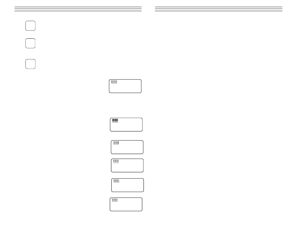
The Display
The numeric portion of the display consists of 4 complete
digits preceded by a leading “1”, and is used to display
numeric values, as well as occasional simple words, to
indicate the status of various settings. When the TI-007DL
is displaying thickness measurements, the display will hold
the last value measured, until a new measurement is made.
Additionally, when the battery voltage is low, the entire
display will begin to flash. When this occurs, the batteries
should be replaced.
These eight vertical bars form the Stability Indicator.
When the TI-007DL is idle, only the left-most bar and the
underline will be on. While the gauge is taking a measure-
ment, six or seven of the bars should be on. If fewer than
five bars are on, the TI-007DL is having difficulty achieving
a stable measurement, and the thickness value displayed will
most likely be erroneous.
When the IN symbol is on, the TI-007DL is displaying a
thickness value in inches. The maximum thickness that
can be displayed is 1.999 inches.
When the MM symbol is on, the TI-007DL is displaying a
thickness value in millimeters. If the displayed thickness
exceeds 19.999 millimeters, the decimal point will shift auto-
matically to the right, allowing values up to 99.99 millime-
ters to be displayed.
When the IN symbol is on, in conjunction with the /µs
symbol, the TI-007DL is displaying a sound-velocity value
in inches-per-microsecond.
When the M symbol is on, in conjunction with the /s
symbol, the TI-007DL is displaying a sound-velocity value
in meters-per-second.
MEM
CLR
SEND
1.8.8.8.8
+
IN
MM/
µ
s
1.8.8.8.8
+
IN
MM
/
µ
s
1.8.8.8.8
+
IN
MM/
µ
s
1.8.8.8.8
+
IN M
M
/
µ
s
1.8.8.8.8
+
IN MM/
µ
s
1.8.8.8.8
+
IN MM/
µ
s
8 .0
APPEN DI X B — APPLI CAT I ON N OT ES
Measuring tubing
When measuring a piece of tubing for wall thickness, it may prove beneficial to have
multiple delay lines with different radiuses for different tubing diameters. The delay
lines can be easily radiused by placing a piece of emery cloth around the tubing and
moving the transducer back and forth until a radius has formed on the tip of the delay
line.
Measuring hot surfaces
The velocity of sound through a substance is dependent upon its temperature. As mate-
rials heat up, the velocity of sound through them decreases. In most applications with
surface temperatures less than about 200 °F (100 °C), no special procedures must be
observed. At temperatures above this point, the change in sound velocity of the materi-
al being measured starts to have a noticeable effect upon ultrasonic measurement.
At such elevated temperatures, it is recommended that the user perform a calibration
procedure (refer to page 6) on a sample piece of known thickness, which is at or near
the temperature of the material to be measured. This will allow the TI-007DL to
correctly calculate the velocity of sound through the hot material.
When performing measurements on hot surfaces, it may also be necessary to use a
specially constructed high-temperature delay line. It is recommended that the probe
be left in contact with the surface for as short a time as needed to acquire a stable
measurement. While the transducer is in contact with a hot surface, it will begin to
heat up, and through thermal expansion and other effects, may begin to adversely
affect the accuracy of measurements.
Measuring laminated materials
Laminated materials are unique in that their density (and therefore sound-velocity)
may vary considerably from one piece to another. Some laminated materials may even
exhibit noticeable changes in sound-velocity across a single surface. The only way to
reliably measure such materials is by performing a calibration procedure on a sample
piece of known thickness. Ideally, this sample material should be a part of the same
piece being measured, or at least from the same lamination batch. By calibrating
to each test piece individually, the effects of variation of sound-velocity will be
minimized.
An additional important consideration when measuring laminates, is that any included
air gaps or pockets will cause an early reflection of the ultrasound beam. This effect
will be noticed as a sudden decrease in thickness in an otherwise regular surface.
While this may impede accurate measurement of total material thickness, it does
provide the user with positive indication of air gaps in the laminate.
– 17 –