Vdc configuration – Aviom 6416i User Manual
Page 52
25
vdc c
oNFigurAtioN
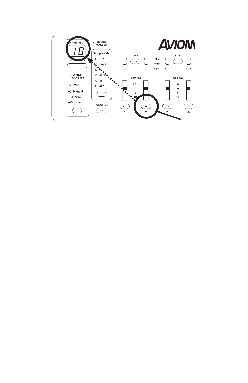
On an input module set to the A-Net Slot range starting at 17, pressing the
Channel 2 button displays A-Net Slot 18 when the module is edit locked.
Pressing the Channel 3 button will display “19,” pressing the Channel 4
button will display “20,” etc.
Channel activation status is not affected by the use of the query function. It
is used for information only.
To exit the query function, press
E
dit
l
oCk
followed by
E
ntEr
to return to
normal operation.
Pro64 modules are set to provide query information whenever the network
is in Managed Mode.
VDC Configuration
Pro64’s Virtual Data Cables provide an easy way to distribute control signals
throughout a network, greatly expanding the possibilities for using and
distributing MIDI, GPIO, and RS‑232 control signals. A‑Net provides the ability
to send these control data over greater distances than previously possible
with traditional analog connections. And with MIDI and GPIO connections,
infinite numbers of copies of the control data are available everywhere in the
network.
Fourteen VDC Slots are available at all times; VDCs are not affected by the
current sample rate or network mode. The makeup of the VDC Slots is user
defined; no VDC Slots are reserved for specific data types.
The VDC interface includes the numeric VDC Slot display, the inc/dec buttons
used for VDC Slot selection, the Assign Port list of VDC data types, and a
selection button for choosing a VDC data type for the currently selected VDC
Slot.