Setting gain, Av-m8 – Aviom AV-M8 User Manual
Page 32
24
Av-M8 M
ic
i
nput
M
odule
u
ser
G
uide
Setting Gain
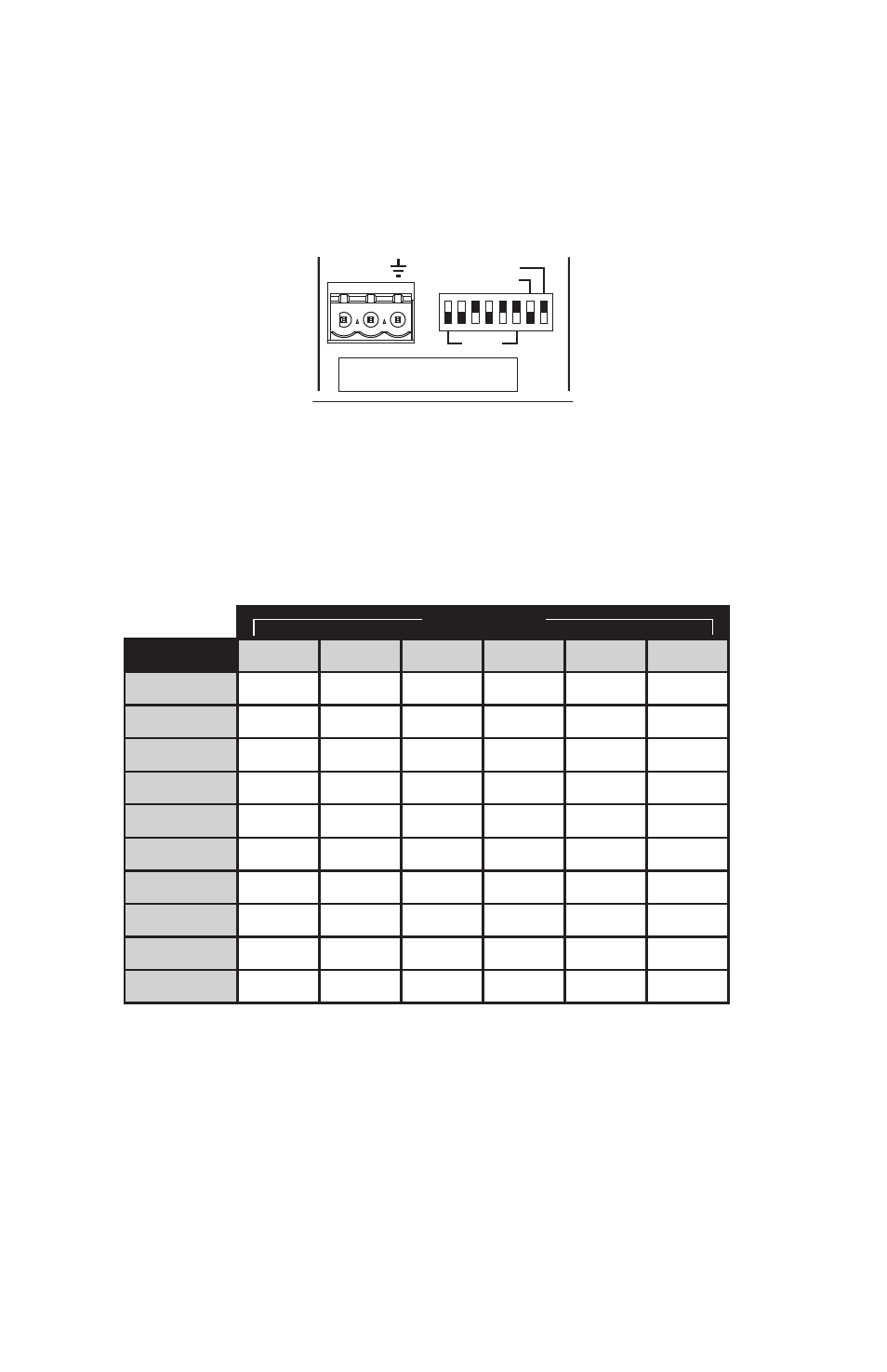
The following table lists the DIP switch settings for input gain. Move the DIP
switch to the up (1) position to activate it.
AV-M8
+16 — 0 0 0 0 0 0
+22 — 0 0 0 0 0 1
+49 — 0 0 1 1 1 1
+54 — 0 1 1 1 1 1
+59 — 1 0 1 1 1 1
+64 — 1 1 1 1 1 1
+39 — 0 0 0 1 1 1
+44 — 0 0 1 0 1 1
+28 — 0 0 0 0 1 0
+34 — 0 0 0 0 1 1
GAIN SETTINGS (dB):
+
GAIN
48V OFF
48V OFF
48V OFF
48V OFF
48V OFF
48V OFF
48V OFF
48V OFF
LO
W C
UT
GAIN
LO
W C
UT
–
+ –
+
GAIN
LO
W C
UT
–
GAIN
LO
W C
UT
+ –
GAIN
LO
W C
UT
+ –
GAIN
LO
W C
UT
+ –
GAIN
LO
W C
UT
+ –
GAIN
LO
W C
UT
+ –
1
0
1
0
1
0
1
0
1
0
1
0
1
0
1
0
PAD (20dB)
48V ON
FLAT
PAD (20dB)
48V ON
FLAT
48V ON
FLAT
48V ON
FLAT
48V ON
FLAT
48V ON
FLAT
48V ON
FLAT
48V ON
FLAT
1
2
3
4
5
6
7
8
Move the Gain DIP switches to the up position to engage them. Shown here
is a +44 dB gain setting, with no phantom power or filter.
In the gain settings table, “0” indicates the down position and “1” indicates
the up position on the DIP switch.
DIP Switch
Gain
1
2
3
4
5
6
+16dB
0
0
0
0
0
0
+22dB
0
0
0
0
0
1
+28dB
0
0
0
0
1
0
+34dB
0
0
0
0
1
1
+39dB
0
0
0
1
1
1
+44dB
0
0
1
0
1
1
+49dB
0
0
1
1
1
1
+54dB
0
1
1
1
1
1
+59dB
1
0
1
1
1
1
+64dB
1
1
1
1
1
1
When using the Pad, found on channels 1 and 2 only, the channel’s initial
input level is decreased by 20dB relative to the settings shown in the table
above.
To use phantom power with a microphone, move the 48V switch to the up
position.
The Low Cut filter can be used to eliminate low frequency artifacts. The Low
Cut is engaged in the down position; the audio signal is unaltered in the up
(Flat) position.