Adat® digital i/o, Clock source, Adat – Aviom AV-M8 User Manual
Page 27: Digital i/o, Av-m8
19
Av-M8 M
ic
i
nput
M
odule
u
ser
G
uide
POWER
ON
EXPANSION
OUT
IN
AV-M8
STEREO LINK
CLOCK SOURCE
INTERNAL
ADAT
CH 9-16
250VAC-F4AL
OUT
ADAT
®
When the Power LED is lit, the AV-M8 is outputting A-Net.
ADAT
®
Digital I/O
The AV‑M8 includes digital I/O designed to allow two AV‑M8 modules to be
linked together, creating a single 16‑channel A‑Net stream. ADAT® Lightpipe®
digital connections are used, allowing simple plug‑and‑play operation when
creating a 16‑channel system.
POWER
ON
EXPANSION
OUT
IN
AV-M8
STEREO LINK
CLOCK SOURCE
INTERNAL
ADAT
CH 9-16
250VAC-F4AL
OUT
ADAT
®
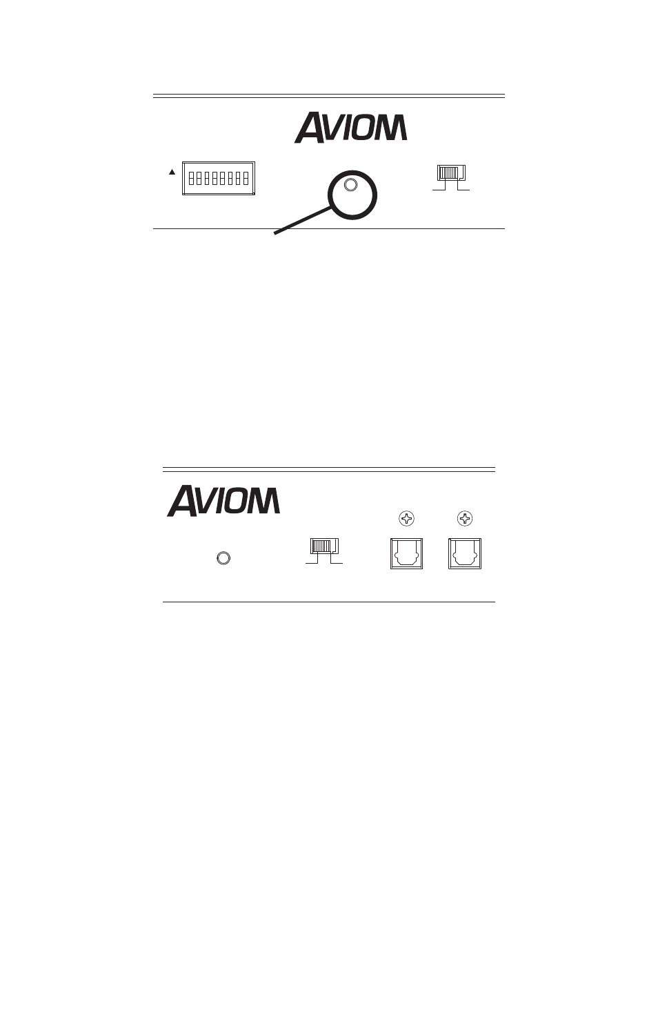
ADAT Clock Source (left) and digital I/O connections (right)
Two Lightpipe connections are provided, In and Out, as well as a clock source
switch that allows the Pro16 network clock source to be set to internal clock
or to the clock imbedded within the ADAT digital signal.
Cables for the ADAT I/O use standard, readily‑available Toslink® connections.
Lightpipe cables of up to three meters in length can be used.
Clock Source
The Clock Source switch selects either the internal A‑Net clock or the clock
imbedded within the ADAT digital signal as the network clock. When only
one AV‑M8 is used, the clock source should be set to Internal. When using two
AV‑M8 modules to create a 16‑channel A‑Net stream, the AV‑M8 receiving
ADAT data should be set to use the ADAT clock.