Internal system wiring diagrams - line voltage, C or higher for field connection of this device, Comfort plus commercial appendix – Steffes 6140 User Manual
Page 27: A.03
Comfort Plus Commercial
Appendix
n
A.03
Appendix
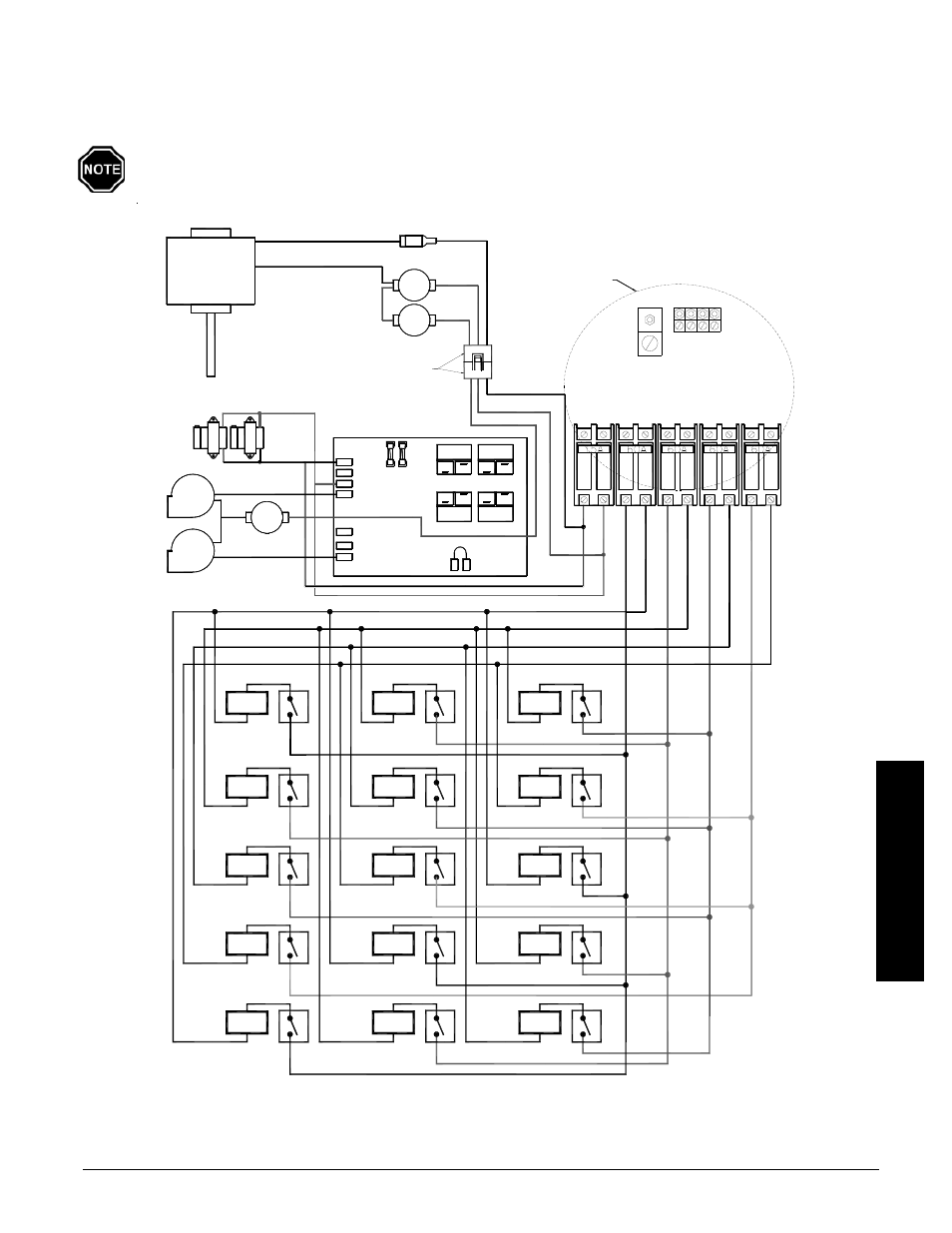
240V OR 208V SYSTEMS ONLY
WITH VARIABLE SPEED
INTERNAL SYSTEM WIRING DIAGRAMS - LINE VOLTAGE
NOTE: Line Voltage Field Wiring Connections - See Figure 12A for information on circuit phas-
ing connections.
Use copper or aluminum conductors rated for 75
o
C or higher for field connection of this device.
BLACK
CORE
Element
#1
Element
#2
Element
#3
Element
#4
Element
#5
Element
#6
#12
#11
#10
Element
#7
Element
#8
Element
#9
Element
Element
Element
Element
#13
Element
#14
Element
#15
BLACK/YELLOW
DAMPER
BASE IO BOARD
RED
BLOWER
BL
OW
ER
S
/
COM
COM
NO
NO
L2 120
RESISTOR
RESISTER
BLOWER
L2 240
BLOWER
160 °
WHITE
N.C.
CORE
BLACK
HEAT CALL
FAN ON
RELAY
BLUE/WHITE
RELAY
NO
NO
COM
COM
5 Amp
L1
240v / 24v
TRANSFORMER
1/4 Amp
BLUE
CH
AR
G
E
CH
AR
G
E
CH
AR
G
E
CI
RC
UIT
CH
AR
G
E
CI
RC
U
IT #
1
CO
NTR
O
LS
CI
RC
U
IT #
2
CI
RC
U
IT #
3
CI
RC
U
IT #
4
BROW
N
BLU
E
BLA
C
K
RED
GROUND
LUGS
N.C.
BLACK
BLACK
BLUE
190 °
BLU
E
/B
LA
C
K
BLUE/WHITE
160 °
N.C.
MANUAL RESET
VARIABLE SPEED BLOWER
Connectors located
Heater & Plenum
in the base of the
9 Pin Header
BL
UE
/B
L
A
C
K
SEE NOTE 2