Important, Low voltage electrical connections - peak control, Installation – Steffes 6140 User Manual
Page 18: Peak control terminal connections figure 13
208/240 SINGLE PHASE
CIRCUIT PHASING CONNECTIONS
FIGURE12A
Installation
n
3.09
Comfort Plus Commercial
Installation
The 60 AMP breakers are for internal
component protection only. Sizing of the
field wire and breaker size MUST be in
compliance with all applicable local,
state, and national codes and regulations.
Circuit Breakers
LIN
E
1
BLOWERS/CONTROLS CIRCUIT
LIN
E
2
LIN
E
1
LIN
E
2
LIN
E
1
LIN
E
2
LIN
E
1
LIN
E
1
LIN
E
2
To Serv
ice
(Break
er) Panel
CHARGE CIRCUIT #4
CHARGE CIRCUIT #3
LIN
E
2
CHARGE CIRCUIT #1
CHARGE CIRCUIT #2
277/480V AND
347/600V
THREE PHASE
FIGURE12B
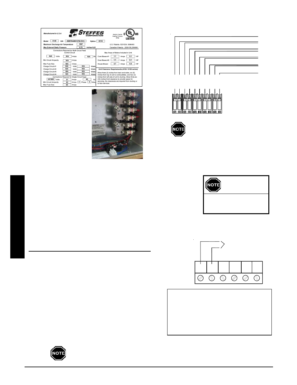
SAMPLE SYSTEM IDENTIFICATION LABEL
FIGURE 11
6-Position Low Voltage Terminal Block Coding
RP = Peak Control Input Common
P = Peak Control Input
AP = Anticipated Peak (Pre-Peak) Control Input
COM = Peak Control Output Common
NC = Peak Control Output (Normally Closed)
NO = Peak Control Output (Normally Open)
LOW VOLTAGE ELECTRICAL CONNECTIONS - PEAK CONTROL
Steffes ETS heating equipment may be controlled by the Power Company via a
peak control signal. This signal can be sent to the equipment using a Steffes
Power Line Carrier control system, low voltage wiring, a Steffes Time Clock
Module, or line voltage control. In applications utilizing automatic charge control,
outdoor temperature information is required and can be received via an outdoor
sensor or power line carrier control system.
The Comfort Plus Commercial system is factory configured for low voltage
peak control and is set to charge when the utility peak control switch
closes. Refer to the Configuration Menu (Pages 3.13-3.14) for information
on configuring the system for the application.
LOW VOLTAGE (HARD WIRED) PEAK CONTROL
If using the low voltage peak control option, the Comfort Plus Commercial
is direct wired to the power company's peak control switch. Field connec-
tions from the peak control switch are made to the low voltage terminal
block through a low voltage knockout located on the left side of the electri-
cal panel.
Step 1 Route a low voltage circuit from the power
companys load control or peak signaling device to
the six (6) position low voltage terminal block inside
the electrical compartment of the Comfort Plus
Commercial system through one of its low voltage
wire knockouts.
Step 2 Connect the field wiring to positions "RP" and "P" on
the six (6) position low voltage terminal block. (See Figure 13.)
To use the system to control other loads, refer to Auxiliary Load Control (Page 3.12).
Low voltage wires
MUST never enter any
line voltage enclosure.
IMPORTANT
PEAK CONTROL
TERMINAL CONNECTIONS
FIGURE 13
NC
P
RP
COM
AP
NO
To Dry Contact Peak
Control Switch