Caution – Steffes 6140 User Manual
Page 16
Installation
n
3.07
Comfort Plus Commercial
Installation
Step 3 Locate the plenum support bracket shipped in the
plenum box. Attach the bracket to the supply air side
using the blunt tip screws supplied in the plenum
assembly hardware package. Refer to Figure 8 for
proper positioning of the plenum support bracket.
Step 4 Attach the supply blower wiring harness located in the
base of the system to the blower using the connections
located on the ends of the harness. Be sure to place any excess
wiring in the base of the system below the radiant heat shield
(Figure 8).
Step 5 Verify that the blower is installed in the plenum with the motor
facing away from the system (Figure 9).
Step 6 Attach the supply air blower plenum to the Comfort Plus Commer-
cial System by drilling two 1/8 holes per edge and using the self
tapping screws supplied in the hardware package.
Step 7 Connect both the return air and supply air ducting systems in the
structure to the system. Be sure the air holes just above the air
outlet on the right side are contained in the duct system. (See
Figure 8 for reference to the location of these holes.)
If the system is installed in an enclosed area (less than 400 square feet), a minimum of a
24"x 24" opening must be installed into the area where the system is located. In
addition, a 6" x 6" non-closing type register can be cut into the return air duct. Refer to
Placement and Clearance Requirements section (Pages 3.02-3.03) for more information.
Step 8 Connect the supply air duct in the structure directly to the system's air outlet located on the top panel.
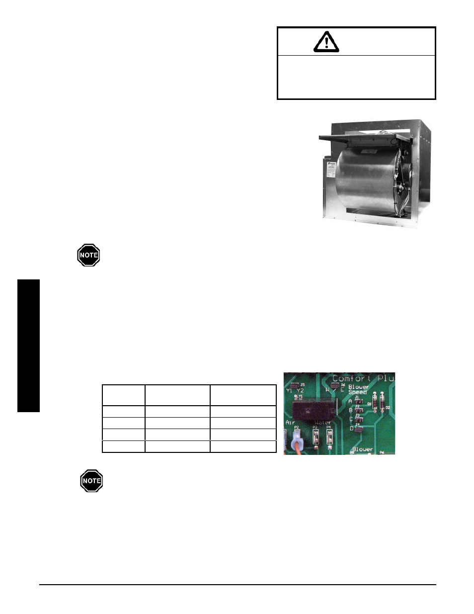
Step 9 Blower speed selection is configured by moving the blower speed jumper (Figure 10) to the desired
position. Reference the System Air Delivery Matrix for CFM information.
Step 10 The W/E jumper (Figure 10) MUST be in the ON position or the blower will not operate with an E call
from the thermostat.
When routing the harness to the supply
air blower, the harness must route to the
side of the air deflector in the bottom of
the supply air blower housing.
CAUTION
w
External static pressure should not exceed .75 inches water column.
w
With 2 stage Heat Pump, a Stage 1 heat call results in 50% of selected CFM.
w
Generally, 400 CFM of air flow is recommended per ton of cooling. Therefore,
a 3-ton heat pump or air conditioner would require 1200 CFM.
FIGURE 9
Jumper
½ HP Variable
Speed CFM
1 HP Variable
Speed CFM
A 1000 1200
B 1200 1400
C 1400 1600
D 1600 2000
SYSTEM AIR DELIVERY MATRIX
VARIABLE SPEED MOTOR
FIGURE 10