Caution, Warning, Brick core temperature sensor installation – Steffes 6140 User Manual
Page 15: Ducting
BRICK CORE TEMPERATURE SENSOR INSTALLATION
Step 1 Remove the screws by the brick core temperature sensor holes in the
galvanized front panel.
Step 2 Insert the brick core temperature sensors through the holes in the
galvanized front panel. Be sure the sensor marked "upper" is installed
in the upper opening , the sensor marked "lower" is installed in the
lower opening, and the sensor marked "middle" is installed in the center
position (Figure7). The sensor must pass through the blanket insulation
and into the brick core. Holes have not been predrilled through the
insulation. Use the sensors to aid in making a passageway by rotating
them side-to-side while gently pushing inward.
Step 3 Once the brick core sensors are installed, put the screws back into
position in the galvanized front panel to hold the sensors in position
and to provide the electrical ground.
Step 4 Check the non-insulated element terminations to make sure they do
not come within 1/2" of any surface area on the system.
Step 5 Re-install painted front panel using previously removed screws.
DUCTING
For air delivery, the Comfort Plus Commercial
System is equipped with a variable speed supply
air blower. When interfacing with a heat pump, the
A-Coil MUST be placed on the return air side.
To maintain a room temperature of 85
o
F or less in
the mechanical room, a 24" x 24" opening can be
installed in the area or a 6" x 6" non-closing
register can be cut into the return air duct. Refer
to Placement and Clearance Requirements (Page
3.02-3.03) for more information.
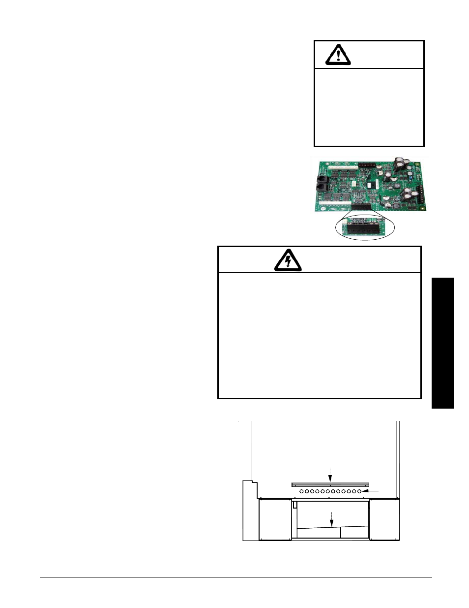
The system is factory configured for a left-to-right
or right-to-left airflow. In either airflow direction,
the holes directly above the air outlet on the right
side of the furnace MUST be contained in the
duct system. (See Figure 8 for reference to these
air holes.)
If a down flow configuration is desired, a down flow kit
must be ordered from the factory (Order Item
#1301578) and the system MUST be raised a minimum
of 10" off the ground. An 18" pedestal is available
(Order Item #1301585).
Step 1 Unbox the supply air blower plenum assembly.
Step 2 Remove and discard metal plate securing
supply air blower to plenum assembly.
Risk of improper operation.
Proper installation of the
brick core temperature
sensor is critical to the
operation of the heating
system. Read and follow
installation instructions
carefully.
CAUTION
Comfort Plus Commercial
Installation
n
3.06
Installation
FIGURE 7
HAZARDOUS VOLTAGE:
Risk of electric shock. Can cause injury or death.
w Do install ducting before energizing the system.
w Do NOT operate the system without ducting in-
stalled to both the air inlet and outlet.
w Proper duct design and air flow are critical to
achieve optimum system performance. A poorly
designed duct system and/or improper air flow can
cause system inefficiencies, air noise, and conden-
sate drain problems. In applications where poor air
flow conditions exist along with high humidity, it
may be necessary to install a secondary conden-
sate drain pan. (Order Item #1301576).
WARNING
SUPPLY AIR PLENUM ATTACHMENT
FIGURE 8
Air
Holes
Plenum Support Bracket
Radiant Heat Shield