Coolant temperature sensor – Dynon Avionics EMS-D10 Installation Guide User Manual
Page 31
Transducer
Installation
ensures that, in the event of a sensor failure, coolant leakage rate is minimized, allowing time for
an emergency landing.
Crimp a standard ¼” female Faston onto one of the
ground wires (see the Grounding section on page 2-2)
coming from the 37-pin harness. Crimp another ¼”
female Faston onto both the wire that corresponds to the
desired GP input and a 1kΩ resistor (color bands:
brown, black, black, brown, brown; connect in either
direction), or splice the resistor into the GP input line
elsewhere on the run. Push the two Fastons onto the two
terminals on the fuel pressure sensor. Polarity is not
important. Connect the other side of the 1kΩ resistor
(color bands: brown, black, black, brown, brown;
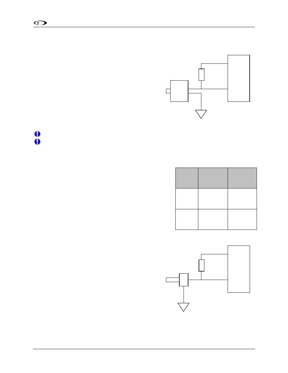
connect in either direction) to the 5V Excitation Circuit, pin 18, as shown in the diagram.
+5V
excitation
GP in
1kΩ
Due to vibration issues, never connect the pressure sensor directly to engine.
If you use Teflon tape or other seal, ensure the sensor casing still maintains a good
connection to ground.
COOLANT TEMPERATURE SENSOR
You will find two 1kΩ resistors (color bands: brown,
black, black, brown, brown; connect in either direction) in
the accessories package (Dynon P/N 100446-000) included
with the EMS-D10. You will be using one of these
resistors for proper installation of your coolant temperature
sensor.
The coolant temperature sensor needs to be installed
according to the directions of your engine’s manufacturer.
Dynon Avionics sells temperature sensors with both 5/8-18
UNF (Dynon P/N 100409-001) and 1/8-27 NPT (Dynon
P/N 100409-000) threads; these are the same as those used
by the oil temperature inputs. If neither of these threads
matches those in your coolant line, you will need to use
adapters or drill/tap your own. Using a crush washer
between the sensor and the mating line, screw the
sensor into the fitting. Do not over tighten.
DB37
EMS
Pin
EMS
harness
Color
Function
Desired
GP
input #
See chart
GP
18 White/Red
5V supply
to 1kΩ
resistor
Route the wire from the desired GP pin on the 37-pin
harness to where the coolant temperature sensor is
mounted. When routing the wires, make sure that they
are secured, so they will not shift position due to
vibration. Strip ¼” of insulation off the end of the wire.
Crimp a #10 ring terminal onto the end of the wire and a
1kΩ resistor (color bands: brown, black, black, brown, brown; connect in either direction), or
splice the resistor into the GP input line elsewhere on the run. Ensure that a good connection is
made between the wire and the connector (and resistor, if spliced in at that point). Unscrew the
Case
grounded
+5V
excitation
GP in
1kΩ
EMS-D10 Installation Guide
3-17