2 front panel, Front panel – CANOGA PERKINS 9145ELB Network Interface Device Hardware User Manual
Page 20
9145ELB NID Hardware User’s Manual
Functional Description
Front Panel
6
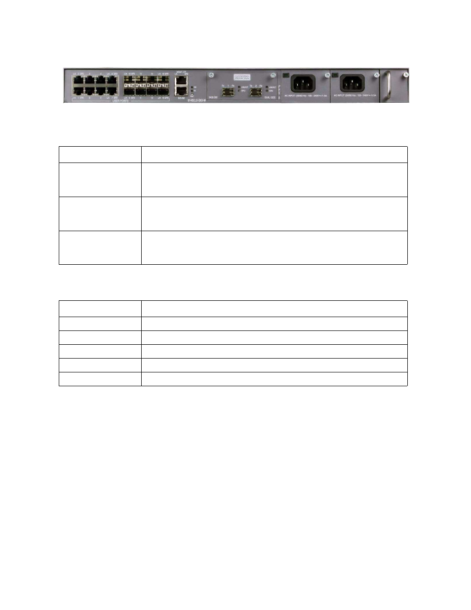
Figure 2-3 Model number 9145ELB-B83-M-0
2.2 Front Panel
The 9145ELB front panel is shown in
. The User Ports, located on the left, consist of
sixteen dual media ports. The Network Ports feature a field replaceable card that can
accommodate different types of uplinks.
All 9145ELB ports and connectors are accessible from the front panel. All front panel modules
(Network Port modules, fan and power modules) are hot swappable.
The 9145ELB front panel has the following features:
•
Sixteen dual media User Ports with SFP and RJ45 connectors. See the section
•
Dual 10G Optical Ethernet Network Port module. See the section
Table 2-1 9145ELB Base Unit Model Numbers and Configuration
Model Number
Extended Description
9145ELB-B81-M-0
9145ELB, 16 User Ports, Local Ethernet Management Port, Console
Port, Requires: Fan Module, Power Supplies, and Network Port Mod-
ule.
9145ELB-B82-M-0
9145ELB, 16 SFP User Ports, Local Ethernet Management Port, Con-
sole Port, Requires: Fan Module, Power Supplies, and Network Port
Module.
9145ELB-B83-M-0
9145ELB, 8 User Ports and 8 SFP User Ports, Local Ethernet Man-
agement Port, Console Port, Requires: Fan Module, Power Supplies,
and Network Port Module.
Table 2-2 9145ELB Module Numbers
Model Number
Description
9420-00
Fan Module
9420-04
AC power supply
9420-05
-48V DC power supply
9420-06
-24V DC power supply
9420-302
Dual 10G Optical Ethernet Module