Chapter 2 set-up and installation, 1set up and install the l357, Chapter 2 set-up and installation -1 – CANOGA PERKINS L357 Gigabit Ethernet Service Unit User Manual
Page 11: Set up and install the l357 -1, Figure 2. switch 1 through 8 locations -1
EdgeAccess Universal Chassis System
L357 Gigabit Ethernet Service Unit
2-1
Chapter 2
Set-up and Installation
This section describes how to set up and install the L357.
2.1
Set Up and Install the L357
Before setting up the L357, make sure the chassis is installed and its Users Manual is available for
reference. If the system includes an optional DMM and CIM(s), make sure these are available:
•
Serial cable (required to connect the chassis to a VT100 type terminal or PC)
•
VT100 type terminal or PC to run the User Interface manager
•
The DMM and CIM manuals
1. Unpack and inspect all components. Save the shipping carton and packing materials in case you
need to return the equipment to the manufacturer. Appendix A provides information for Return
Material Authorization (RMA).
2. Before inserting the L357, check the front panel to verify that the L357 provides the wavelength
that matches its link partner.
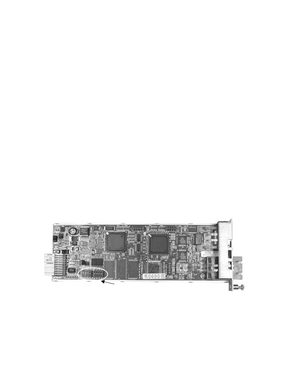
3. For installation in a UCS 1001 or a Model 1030 enclosure, or if you plan to use the Hardware
Option Control (see Section 4.5.2), set Switches 1 through 6 (Switches 7 and 8 are not used); see
Figure 2 and Tables 1 and 2. For more information about the hardware switch functions, see
Section 3.3.
Note: An L357 with a fiber User port ignores the settings for User Port Speed/Duplex.
An L357 with a UTP User port ignores the setting for the LLE User Port hardware switch.
Switch 1 through Switch 8
Figure 2. Switch 1 Through 8 Locations