Carrier Compressor and Condensing Unit User Manual
Page 6
6
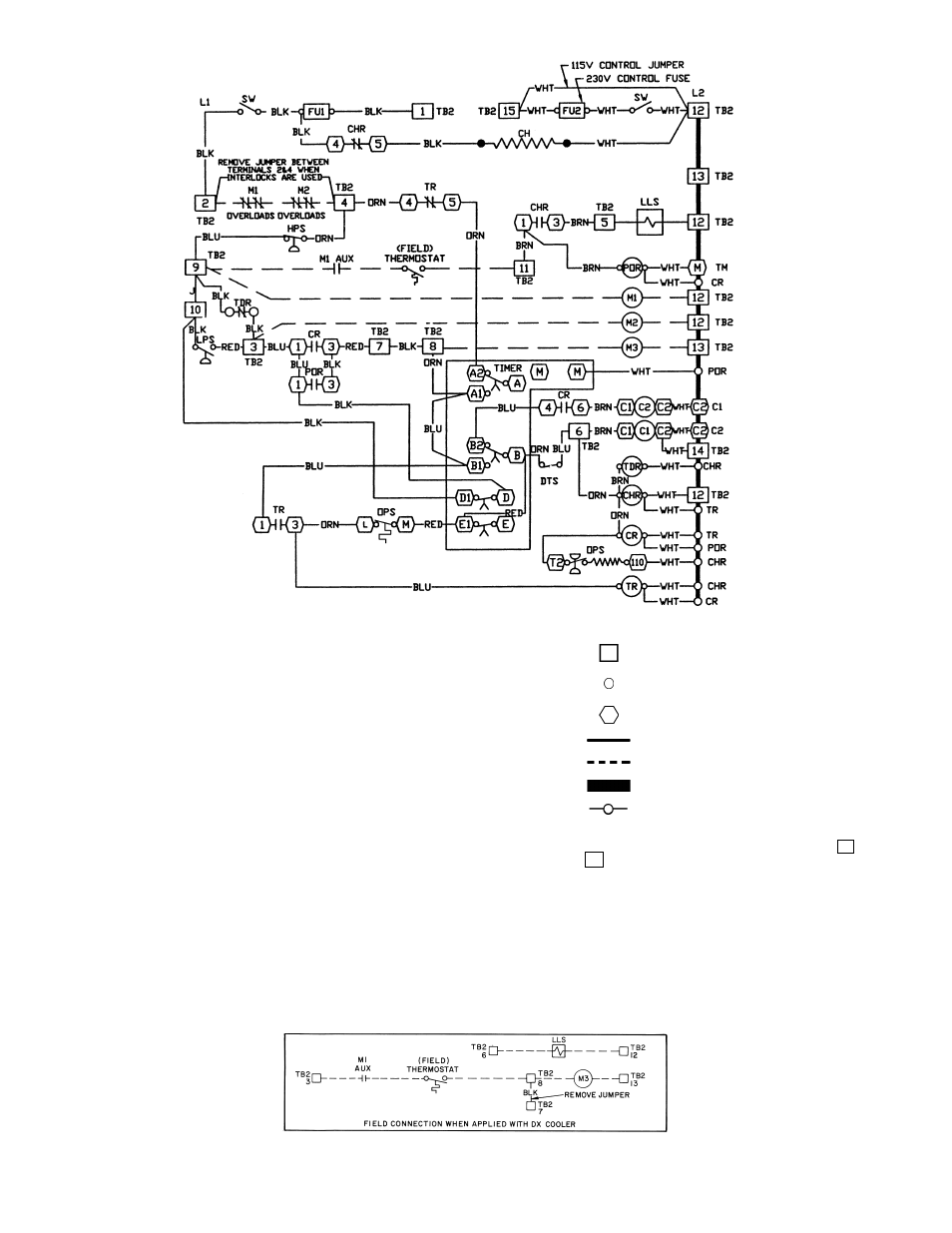
Fig. 6 — Control Circuit Wiring for 06E/07E Units
AUX
— Auxiliary
C
— Compressor Contactor
C1
— Compressor Contactor
(XL start and first step of PW start)
C2
— Compressor Contactor
(PW second step)
CH
— Crankcase Heater
CHR — Crankcase Heater Relay
CR
— Control Relay
DTS
— Discharge Temperature Sensor
DX
— Direct Expansion
FU
— Fuse
HPS
— High-Pressure Switch
LLS
— Liquid Line Solenoid Valve
LPS
— Low-Pressure Switch
Terminal Block Connector
Unmarked Terminal
Marked Terminal
Factory Wiring
Field Control Wiring
To indicate common potential only;
not to represent wiring.
Splice
NOTES:
1. Factory wiring is in compliance with NEC. Any field modifications
or additions must be in compliance with all applicable codes. Use
copper, copper-clad aluminum for field power supply only.
2. Field power supply wiring must be 75 C minimum.
3. Compressor thermally protected. Three-phase motors are pro-
tected against primary single-phasing condition.
4. Pilot duty control must be field supplied. Minimum contact rating
must be 25 va.
5. 60 Hz units have 120 volt control circuit. 50 Hz units have 230 volt
control circuit. A separate source of supply at the correct voltage
must be field supplied supply at the through a fused disconnect
device with a maximum rating of 15 A to TB2 connections
(Hot Side) and
(Neutral).
6. Open control circuit disconnect switch for servicing only. Discon-
nect must remain closed for crankcase heater to operate.
7. A transformer of the following rating may be field supplied for
60 Hz units: 350 va.
8. Transformer must be fused and grounded per applicable codes.
9. If any of the original wiring furnished must be replaced, it must be
replaced with 90 C wire or its equivalent.
10. Wiring is shown for single pumpout control. Single pumpout
control should not be used on direct-expansion (DX) cooler appli-
cations (see lower diagram for wiring when applied with DX
cooler).
L1
L2
M1
— Evaporator Fan or
Chilled Water Pump
M2
— Cooling Tower Pump
M3
— Cooling Tower Fan
NEC — National Electrical Code
OPS — Oil-Pressure Switch
POR — Pumpout Relay
PW
— Part Wind
SW
— Start-Stop-Reset Switch
TB
— Terminal Block
TDR
— Time Delay Relay
TM
— Timer Motor
TR
— Timer Relay
XL
— Across-the-Line
LEGEND