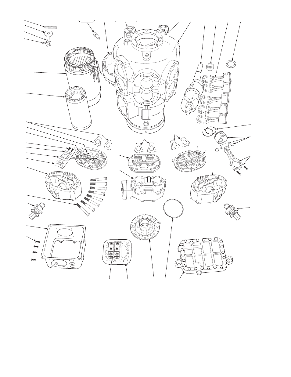
Fig. 11 — compressor components (06e shown) – Carrier Compressor and Condensing Unit User Manual
Page 12
12
34
35
36
37
38
40
41
29
30
28
27
13
11
12
41
24
25
26
7
8
9
31
32
33
1
2
5
6
3
4
14
15 16 17 18
19
10
20
21
23
22
31
31
32
33
38
32
39
LEGEND
1 — Stator (Compressor Motor)
2 — Rotor (Compressor Motor)
3 — Motor Key
4 — Rotor Plate Washer
5 — Rotor Lock Washer
6 — Rotor Lock Bolt
7 — Motor Lock Bushing
8 — Roll Pin
9 — Acorn Nut and Gasket
10 — Compressor Crankcase
11 — Bottom Cover Plate
12 — Crankcase Oil Filter Screen
13 — Pump End Bearing Head Assembly
14 — Motor End Cover
15 — Oil Sight Glass Assembly
16 — Oil Sight Glass O-Ring Gasket
17 — Oil Sight Glass Screw
18 — Oil Sight Glass Lock Washer
19 — Pipe Plug (Hex Head)
20 — Crankshaft
21 — Ring Spacer (when required)
22 — Bearing Washer
23 — Connecting Rod and Piston Assembly
24 — Connecting Rod and Cap Assembly
25 — Piston, Piston Pin and Retaining Ring
Package
26 — Piston Rings (Oil and Compression)
27 — Terminal Plate Assembly
28 — Terminal Bolt Assembly
29 — Terminal Box
30 — Terminal Box Mounting Screw (4)
31 — Suction Valve
32 — Valve Plate Assembly (includes dis-
charge valves)
33 — Cylinder Head Gasket
34 — Cap Screw, Valve Stop
35 — Valve Stop Support
36 — Discharge Valve Stop
37 — Discharge Valve
38 — Cylinder Head (Capacity control,
side bank)
39 — Cylinder Head (Center bank)
40 — Cylinder Head Bolt (8 per head)
41 — Capacity Control Valve (Pressure
type shown)
Fig. 11 — Compressor Components (06E Shown)