Installation manual, Ma 3 transformer kits description, Installation – Rane MA 3 2003 version User Manual
Page 7: 32 1 figure 1. capacitor clearance
TF 407 & TF 410
MA 3 TRANSFORMER KITS
Description
Up to three optional 70.7 V or 100 V constant-voltage distribution transformers may be
mounted inside the MA 3 with no external wiring or mounting required.
• The TF 407 is a 40W, 70.7 V transformer with 0.5 dB insertion loss at rated power and a frequen-
cy response of 50 Hz to 15 kHz, ±1 dB.
• The TF 410 is a 40W, 100 V transformer with 0.5 dB insertion loss at rated power and a frequen-
cy response of 50 Hz to 15 kHz, ±1 dB.
Installation
WARNING — Only authorized service personell should perform this upgrade.
1. Unplug the MA 3 amplifier!
2. Remove the top cover (12 screws).
3. Capacitors C63, C61, C62 and C65 need to be laid toward the rear of the unit (Figure 1). Don’t
press on parts, just gently lay them over.
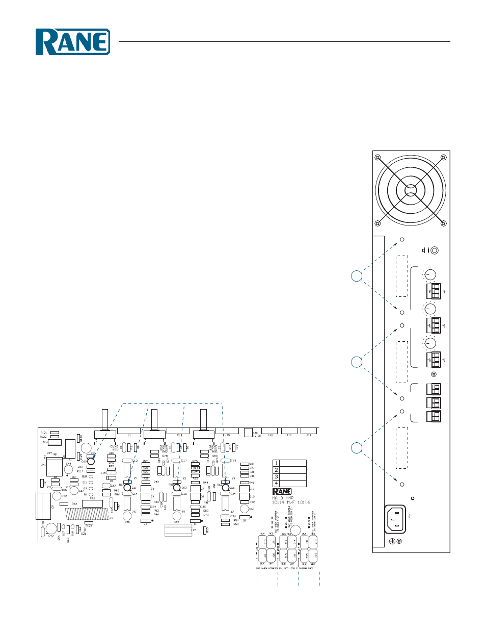
4. Stand the MA 3 up on one end with the power transformer toward the bench (Figure 2).
5. Locate the transformer mounting holes along the rear panel of the MA 3 (Figure 2).
6. Place one of the two supplied #8 screws in the “top” mounting hole of the pair of holes associated
with the channel receiving the transformer (Figure 2).
The “bottom” two holes are for Channel 3.
The “center” two holes are for Channel 2.
The “top” two holes are for Channel 1.
7. With the transformer primary (WHT & BLK) wires facing the PCB, “hang” the transformer on
the #8 screw and nylock nut. Hold the screw and transformer in place with one hand. Use your
other hand to rotate the supplied #8 nut onto the threads. Use a nut driver and #2 Phillips driver
to snug the hardware. Install the second #8 screw and nylock nut. Make sure hardware is tight.
8. Repeat for additional Channels if more than one transformer is required. When installing more
than one, start at the bottom (Channel 3).
Figure 2. Transformer mounting
holes for each channel.
INSTALLATION MANUAL
Gently lay capacitors back toward the rear
Ch 1 Ch 2 Ch 3
360
W
ATTS
120V 50/60 Hz
N108
OUTPUT POWER
PER CHANNEL
40
W
ATTS / 8 OHMS
60
W
ATTS / 4 OHMS
MA
Y USE CLASS 2 WIRING
LEVEL
+
-
+
-
+
+
+
+
-
-
-
-
+
+
+
-
-
-
+
-
+
-
+
-
NORMAL
FA
ST
10
0
LEVEL
LEVEL
10
0
10
0
FOR CONTINUED GROUNDING PROTECTION DO NOT REMOVE SCREW
M
A
3
MADE IN U.S.A.
RANE CORP
.
A
V
IS
RISQUE DE CHOC ELECTRIQUE — NE P
AS OUVRIR
W
A
R
N
IN
G
TO
REDUCE
THE
RISK
OF
FIRE
OR
ELECTRICAL
S
H
O
C
K
D
O
N
O
T
E
XP
O
S
E
TH
IS
E
Q
U
IP
M
E
N
T
TO
RAIN
OR
MOISTURE.
DO
NOT
REMOVE
COVER.
NO
USER
SER
VICEABLE
PA
R
TS
INSIDE.
REFER
SER
VICING TO QUALIFIED PERSONNEL.
CH
3
C
H
2
C
H
1
OUTPUTS
INPUTS
CHANNEL
1
CHANNEL
2
CHANNEL
3
F
AN SPEED
3
2
1
Figure 1. Capacitor clearance