Manual-3 rear panel description – Rane MA 3 2003 version User Manual
Page 5
Manual-3
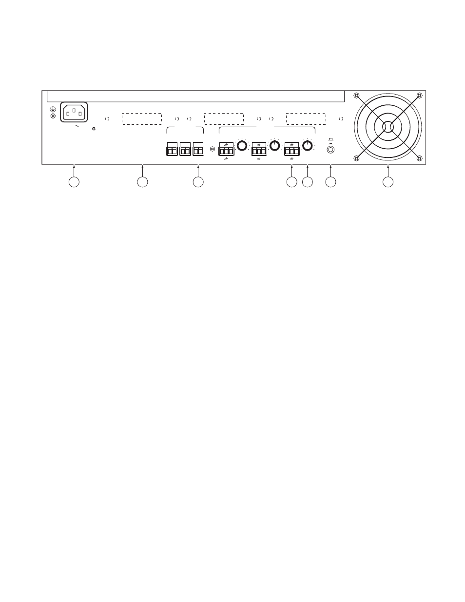
REAR PANEL DESCRIPTION
IEC cord socket:
This connector accepts a standard IEC line cord (included with 120 V domestic units). Plug this into a ground-
ed AC outlet of 120 VAC (or 230 VAC if the MA 3 is internally wired for 230 V operation).
OUTPUTS:
Connect the speaker(s) to each of the three channels by means of the Euroblock connectors with 18 to 12 AWG
wire. Each Output may have an optional 70.7V or 100V distribution transformer installed inside the MA 3. These optional trans-
formers are 40 watt devices with 0.5 dB insertion loss at rated power and a frequency response of 50 Hz to 15 kHz, ±1 dB. The
70.7 V transformer kit is the TF 407. The 100V transformer kit is the TF 410.
INPUTS
are balanced Euroblock connectors, one for each channel. We recommend the use of at least 18 AWG wire for reliabil-
ity. Driving the MA 3 from a balanced source is recommended. If you must drive the MA 3 Input with an unbalanced source, we
recommend using a cable that has two conductors plus a shield. Connect the (+) or “hot” source to the MA 3 (+) Input, the ground
to the MA 3 (–) Input and connect the shield to the MA 3 shield input. Do not connect the shield on the source end. Shield con-
nections go directly to chassis ground and should not be used as signal ground. Shield connection to chassis occurs via the screw
found between the Input and Output connectors—keep this screw tight for improved EMI protection. When operating the MA
3 with unbalanced Inputs, be sure to keep cable lengths as short as possible. Refer to the RaneNote “Sound System Interconnection”
(included in this booklet) for additional information.
LEVEL
controls adjust the input sensitivity for each of the three Amplifiers. The internal Limiters have maximum operating
range (most amount of limiting before input overload) when the LEVEL controls are set to maximum. For best system noise per-
formance, the input sensitivity may be reduced to send a “hotter” signal to the Amplifier. Here we go again! You get nothing for
free. There are always tradeoffs to be made (better overdrive capability or lower system noise). The choice depends on your applica-
tion. For additional information see the RaneNote “Setting Sound System Level Controls” available from our website or upon request
from the factory.
FAN SPEED:
There are two fan speeds. The NORMAL setting (switch out) allows the MA 3 to deliver full rated continuous
average power into 4 ohms, all channels driven, with ambient room temperature of 22°C. Therefore, it is seldom, if ever, necessary
to run the fan at the FAST speed. The exception might be a very hot environment and heavily compressed music into a demanding
load. The only penalty for running the fan at the FAST speed is noise.
Heat tunnel air intake:
The fan draws air in through the finger guard on the rear of the unit. The air flow is directed down a
sealed heat tunnel and exhausts through front panel vents. No filter is required as air flow is directed through an unobstructed,
sealed tunnel and will not contaminate internal circuitry.
Optional internal transformers:
The dotted lines represent areas reserved for the screws and labels that come with internally
mounted transformers. See the next page for more information.
360 WATTS
120V
50/60 Hz
N108
OUTPUT POWER
PER CHANNEL
40 WATTS / 8 OHMS
60 WATTS / 4 OHMS
MAY USE CLASS 2 WIRING
LEVEL
+
-
+
-
+
+
+
+
-
-
-
-
+
+
+
-
-
-
+
-
+
-
+
-
NORMAL
FAST
10
0
LEVEL
LEVEL
10
0
10
0
FOR
CONTINUED
GROUNDING
PROTECTION
DO NOT
REMOVE SCREW
MA 3
MADE IN U.S.A.
RANE CORP.
AVIS
RISQUE DE CHOC ELECTRIQUE — NE PAS OUVRIR
WARNING
TO REDUCE THE RISK OF FIRE OR ELECTRICAL
SHOCK DO NOT EXPOSE THIS EQUIPMENT TO
RAIN OR MOISTURE. DO NOT REMOVE COVER.
NO USER SERVICEABLE PARTS INSIDE. REFER
SERVICING TO QUALIFIED PERSONNEL.
CH 3
CH 2
CH 1
OUTPUTS
INPUTS
CHANNEL 1
CHANNEL 2
CHANNEL 3
FAN SPEED
7
1
2
4
3
5
6