Manual-4 features & applications – Rane MA 3 2003 version User Manual
Page 6
Manual-4
FEATURES & APPLICATIONS
Built to be driven hard
The MA 3 Amplifier drives all three channels at the continu-
ous average rated power, indefinitely. It is specifically designed to
operate in demanding commercial applications. Very low emis-
sions allow the Amplifier to operate in close proximity to signal
processing equipment without causing excessive interference. The
CP 52, CP 64, DA 26 and SRM 66 may all operate next to the
MA 3 in a rack. The high efficiency “heat tunnel” design allows
the Amplifier to process severely compressed signals reliably even
when installed in a rack with elevated ambient temperatures.
Forced air cooling keeps heat away from other equipment.
You won't hear other Zones
The MA 3 is designed to deliver foreground music, back-
ground music and paging signals to three different Zones
without annoying crosstalk. A quiet office, for example, with a
paging signal only, will not hear foreground music playing in the
lounge. The high capacity linear power supply incorporates three
independent secondary supplies with independent bridge recti-
fiers and filters. The result is exceptionally good crosstalk figures
even with multiple channels driving full power into 4 ohm loads.
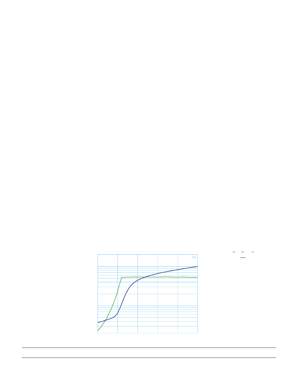
It’s OK to light the 0 dB Headroom indicator a lot
The high performance Limiter used in the MA 3 means all
the available power can be delivered to the load and not simply
held in reserve to avoid overload. There is no need to buy up to
four times the required power just to prevent occasional system
overload. The MA 3 can compress a signal with 9 dB of dynamic
power range down to a signal with 3 dB of dynamic power with-
out loss of speech intelligibility or excessive distortion.
With typical Amplifiers, when 40 watts is needed to achieve
a required average SPL of 80 dB, the contractor must buy an
Amplifier rated at no less than 160 watts just to maintain 6 dB
of headroom. The figure below illustrates the performance of the
MA 3 Limiter.
No bad “spikes”
The MA 3 is designed to operate without interruption of sig-
nal with as little as 85 VAC available (120 VAC unit). Even if the
Amplifier is operating at full power, the signal will not breakup
as the AC line voltage drops to 85 VAC. If the AC line drops
lower than 85 VAC the signal mutes without “spikes.” Once AC
power is restored, the signal restarts quickly without “spikes” or
signal breakup.
The good “SPiKe”
The power Amplifiers in the MA 3 are protected with Na-
tional Semiconductors’ proprietary SPiKe* protection circuitry.
SPiKe protection offers a level of protection not available in
conventional amplifiers. It has the ability to instantaneously
monitor the temperature of the power device die, yielding a level
of reliability not achievable with discrete designs.
80 Hz Highpass Filters
Internal jumpers allow independently selecting 80 Hz,
2
nd
-order Butterworth Filters for each channel. These Filters are
useful when using small bookshelf speakers or small constant
voltage distribution transformers. See the enclosed schematic for
locations of these jumpers.
Optional constant voltage distribution transformers
Up to three 70.7 V or 100 V constant voltage distribution
transformers may be mounted inside the MA 3. The optional
TF 407 is a 40 watt, 70.7 V transformer with 0.5 dB insertion
loss at rated power and a frequency response of 50 Hz to 15 kHz,
±1 dB. The optional TF 410 is a 40 watt, 100 V transformer
with .5 dB insertion loss at rated power and a frequency response
of 50 Hz to 15 kHz, ±1 dB. No external wiring or mounting is
required.
106715
©Rane Corporation 10802 47th Ave. W., Mukilteo WA 98275-5098 TEL 425-355-6000 FAX 425-347-7757 WEB www.rane.com
*Spike is a registered
trademark of National
Semiconductor Corpora-
tion. SPiKe is an acronym
for Self Peak Instanta-
neous (Ke) protection
circuitry.
THD+N(%) & LEVEL(W) vs AMPL(dBu) 31 MAR 98 08:52:13
0.02
0.1
1
2
10
15
20
25
30
35
40
45
50
55
60
-5
0
5
10
15
20
Input Level in dBu
MA 3 Limiter
O
u
tp
u
t
P
o
w
er
in
W
at
ts
TH
D
&
N
o
is
e
in
%
Po
w
er
T
HD
&
N
oi
se