Manual-2 front panel description – Rane MA 3 2003 version User Manual
Page 4
Manual-2
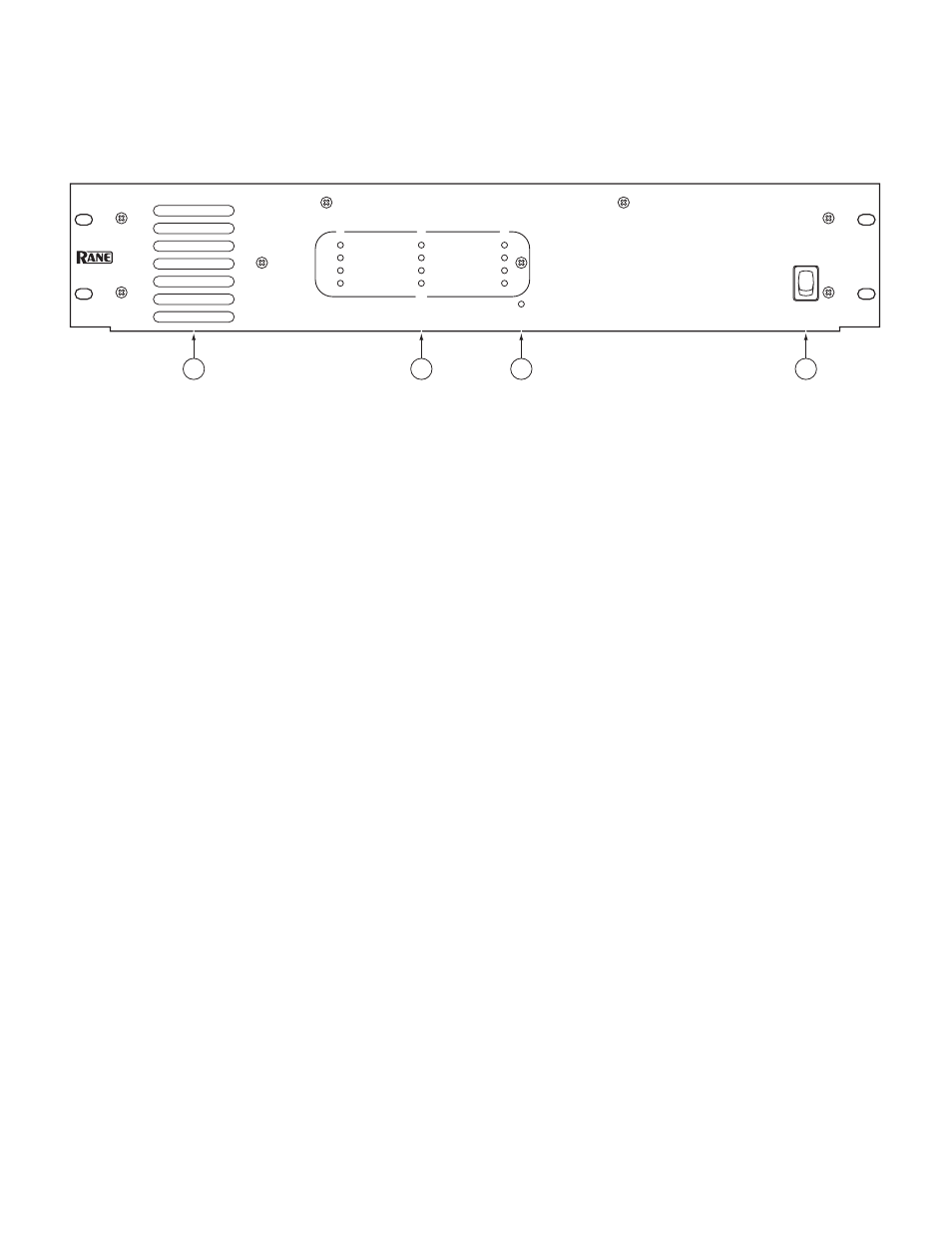
FRONT PANEL DESCRIPTION
Heat tunnel exhaust vents
are located on the left of the unit. Large aperture vent slots are used for low noise. Air is taken in at
the back of the unit and exhausts out the front. When installed in a rack, make sure there is ample room for air to exit. The sealed
heat tunnel design does not require the use of an air filter.
CHANNEL OUTPUT HEADROOM meters
indicate the amount of remaining headroom (how much more signal can be ap-
plied before Limiting occurs).
0 dB
remaining is indicated by a red indicator. When lit, any additional signal causes the Limiter to operate. It is possible to “com-
press” the signal as much as 20 dB with very little effect on sound quality. This gives the MA 3 the overload characteristics of a
much larger amplifier, without the use of external compressors. The MA 3 was designed to be driven hard (heavily compressed
signal) so it is not necessary to buy extra power to obtain the headroom required to prevent overload.
3 dB
remaining is indicated by a yellow indicator. When lit, 3 dB of additional signal may be applied before Limiting.
6 dB
remaining is indicated by a green indicator. When lit, 6 dB of additional signal may be applied before Limiting.
12 dB
remaining is indicated by a green indicator. When lit, 12 dB of additional signal may be applied before Limiting.
POWER:
This yellow indicator lights when power is applied to the unit. See below.
POWER switch:
This control obediently turns the MA 3 on and off every time you poke it with your finger. Poking the top half
of the switch turns the unit on when it is off. Poking the bottom portion of the switch turns the unit off when it it on. All three
channels have turn-on and turn-off muting to reduce switching transients.
MULTICHANNEL
AMPLIFIER
6
12
3
12
6
3
0
0
6
12
3
0
1
2
dB
MA 3
3
CHANNEL OUTPUT HEADROOM
POWER
POWER
2
1
3
4