Manual, Rear panel: stereo 3-way installation – Rane AC 23B (2003 version) User Manual
Page 7
Manual-
MONO 5W (CHANGE INTERNAL SWITCH FOR MONO 4W)
HI MID OUT-5W
LOW OUT
HIGH OUT
OMIT-4W
OMIT MONO
ACN 001 345 482
MADE IN U.S.A.
RANE CORP.
LOW-3W / OMIT-2W
MID-3W / LOW-2W
HIGH OUT
3W
2W
CHANNEL 2
STEREO
CHANNEL 1
STEREO
MONO
MONO 4W / 5W IN
OMIT MONO
SUB OUT
MID OUT
LOW-3W / OMIT-2W
MID-3W / LOW-2W
3W
2W
STEREO
STEREO 3W / 2W
HIGH OUT
PIN 3=NEGATIVE
PIN 1=CHASSIS GND
PIN 2=POSITIVE
AC 23B
CLASS 2 EQUIPMENT
CHANNEL 2 IN
CHANNEL 1 IN
MONO: SET SWITCHES AS SHOWN
260mA
POWER
6
Stereo 3-Way labels in this row.
3
8 9
7
High Amp
Right Input
Mid Amp
Left Input
4
Low Amp
5
3
High Amp
Mid Amp
4
Low Amp
5
1
2
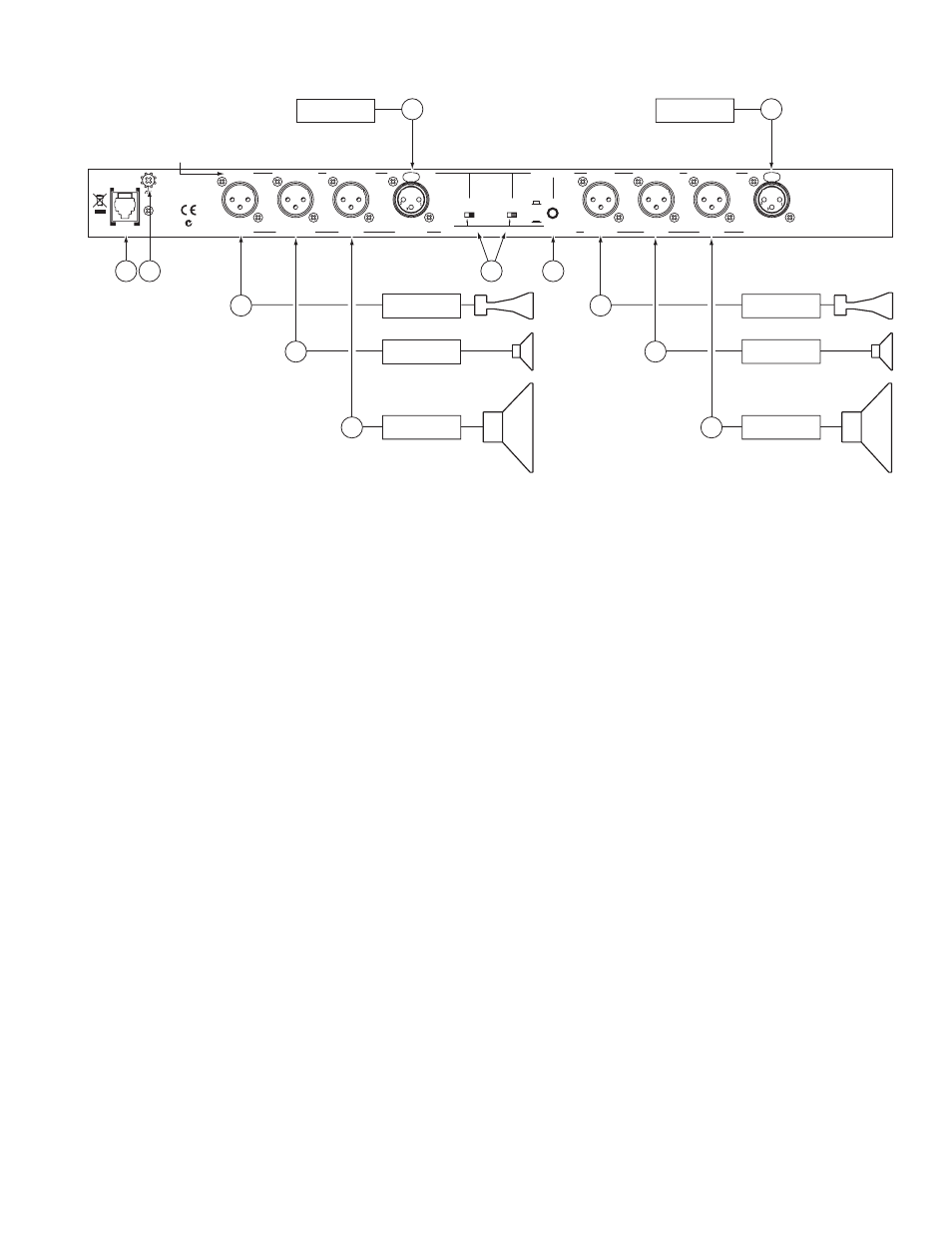
REAR PANEL: STEREO 3-WAY INSTALLATION
Observe the labels above the Inputs and Outputs for Stereo operation.
1
CHANNEL 1 INPUT:
Plug the left output of the mixer, equalizer or other signal source to this Input. Pin 2 is “hot” per AES
standards.
2
CHANNEL 2 INPUT:
Plug the right output of the mixer, equalizer or other signal source to this Input.
3
HIGH OUTPUTS:
Connect the CHANNEL 1 HIGH OUT to the left channel input of the high frequency amp, and the
CHANNEL 2 HIGH OUT to the right channel input of the high frequency amp.
4
MID OUTPUTS:
Connect the CHANNEL 1 MID OUT to the left channel of the mid frequency amp, and the CHANNEL 2
MID OUT to the right channel of the mid frequency amp.
5
LOW OUTPUTS:
Connect the CHANNEL 1 and 2 LOW OUTS to the left and right channels of the low frequency amplifier,
respectively. If you need a summed Mono Low Ouput, see ‘Monoing the Low Outputs’ on page Manual-7.
6
STEREO/MONO switch:
Set this switch to the STEREO position.
7
2-WAY/3-WAY switch:
Converts the outputs from Stereo 3-Way to Stereo 2-Way. Be sure the switches are in the 3-WAY position.
8
POWER input connector:
Use only a model RS 1 or other power supply approved by Rane. This unit is supplied with a remote
power supply suitable for connection to this input jack. This is not a telephone jack. The power requirements call for an 18-24 VAC
center-tapped transformer only. Using any other type of unapproved supply may damage the unit and void the warranty. Two
years parts and labor is worth safeguarding.
9
Chassis ground point:
A #6-32 screw is used for chassis grounding purposes. Always connect the crossover chassis to the ampli-
fier chassis. See ‘Chassis Grounding’ on page Manual-1 for details.