Rane AC 23B (2003 version) User Manual
Page 11
Manual-
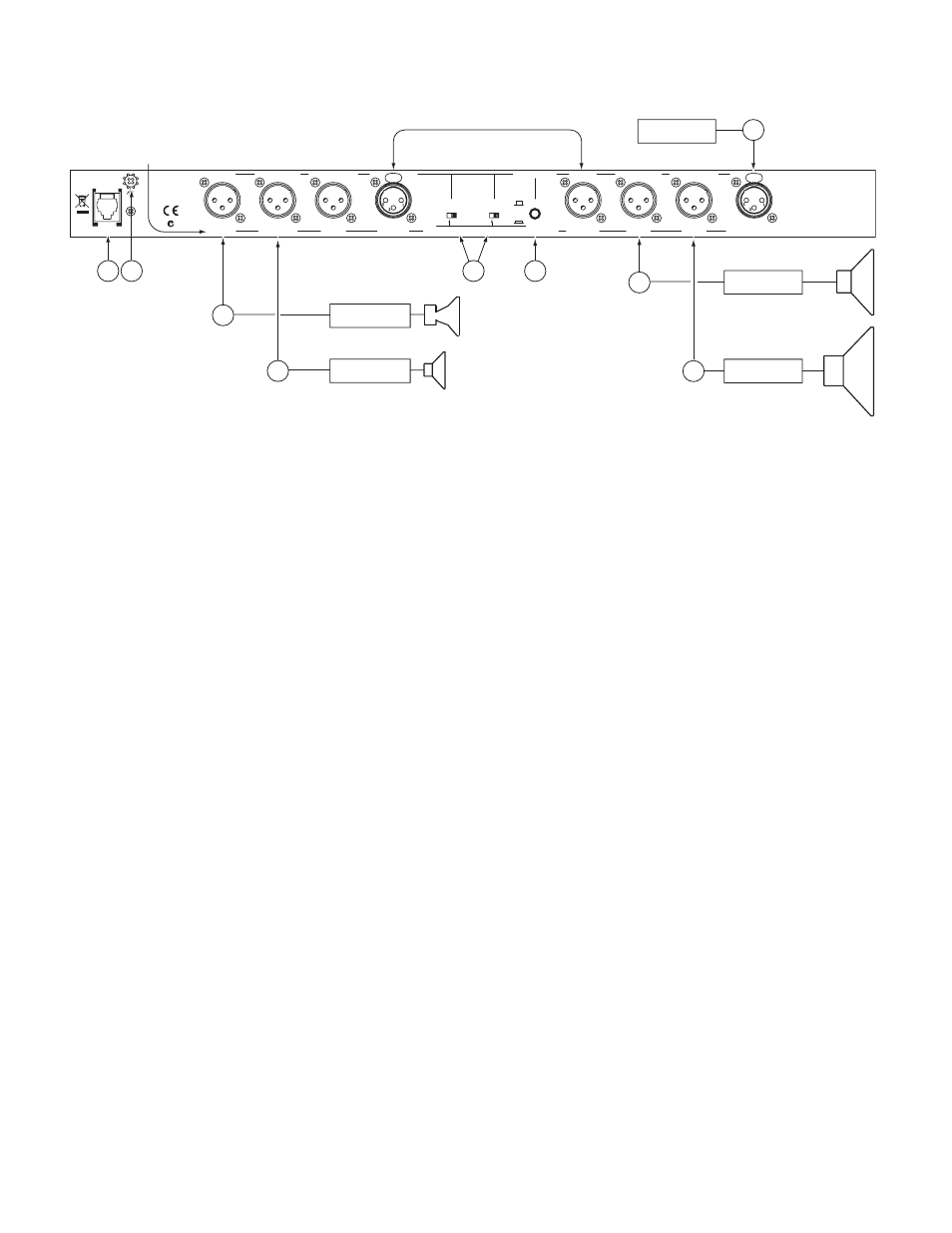
REAR PANEL: ALTERNATE MONO 4-WAY INSTALLATION
Note: The switching in the AC 23B will result in a Mono 4‑Way configuration with the crossover ranges SUB, LOW, MID
& HIGH from left to right across the bottom front panel. By connecting a patch cable from the CHANNEL 1 HIGH OUT
to the CHANNEL 2 INPUT, the LOW / MID crossover range changes from
70 Hz‑1 kHz to a higher range of 190 Hz‑7 kHz. Switch CHANNEL 1 to 3‑Way, and CHANNEL 2 to 2‑Way.
Note: DO NOT follow the Mono 4-Way Switch Instructions on page Manual-7, it must be set to 5-Way.
1
MONO INPUT:
Connect the output from your mixer or other signal source only to the CHANNEL 1 INPUT; do not use the
Channel 2 Input. Note: For this alternate Mono 4-Way installation, connect a patch cord from the CHANNEL 1 HIGH OUT to the
CHANNEL 2 INPUT as shown. Pin 2 is “hot” per AES standards.
2
SUBWOOFER OUTPUT:
Connect the SUB OUT to the input of the subwoofer amplifier (or bass bin amp).
3
LOW OUTPUT:
Connect the MID OUT to the input of the low frequency amplifier.
4
MID OUTPUT:
Connect the HIGH-MID OUT to the input of the mid frequency amplifier. Be sure the CHANNEL 1 HIGH
LEVEL and the CHANNEL 2 MASTER LEVEL controls are set at “7” for unity gain between Channels.
5
HlGH OUTPUT:
Connect the HIGH OUT to the input of the high frequency amplifier.
6
STEREO-MONO switch:
Be sure this switch is in the STEREO out position. Yes, STEREO. A Mono circuit is created when
Channel 1 is patched into Channel 2, and the correct signal flow depends on this switch.
7
2-WAY / 3-WAY switches:
Converts each channels outputs from 3-Way to 2-Way. For this configuration, set CHANNEL 1 to 3-
Way, and CHANNEL 2 to 2-Way.
8
POWER input connector.
Use only a model RS 1 or other power supply approved by Rane. This unit is supplied with a remote
power supply suitable for connection to this input jack.
9
Chassis ground point.
A #6-32 screw is used for chassis grounding purposes. Always connect the crossover chassis to the ampli-
fier chassis. See ‘Chassis Grounding’ on page Manual-1 for details.
MONO 5W (CHANGE INTERNAL SWITCH FOR MONO 4W)
HI MID OUT-5W
LOW OUT
HIGH OUT
OMIT-4W
OMIT MONO
ACN 001 345 482
MADE IN U.S.A.
RANE CORP.
LOW-3W / OMIT-2W
MID-3W / LOW-2W
HIGH OUT
3W
2W
CHANNEL 2
STEREO
CHANNEL 1
STEREO
MONO
MONO 4W / 5W IN
OMIT MONO
SUB OUT
MID OUT
LOW-3W / OMIT-2W
MID-3W / LOW-2W
3W
2W
STEREO
STEREO 3W / 2W
HIGH OUT
PIN 3=NEGATIVE
PIN 1=CHASSIS GND
PIN 2=POSITIVE
AC 23B
CLASS 2 EQUIPMENT
CHANNEL 2 IN
CHANNEL 1 IN
MONO: SET SWITCHES AS SHOWN
260mA
POWER
7
Mono 4- and 5-Way labels in this row.
5
8 9
6
High Amp
Mid Amp
Input
Patch Cable
4
Low Amp
3
Sub Amp
2
1