Ac 23b, Operators manual, Manual – Rane AC 23B (2003 version) User Manual
Page 3: Active crossover, Quick start, Wear parts: this product contains no wear parts
Manual-
AC 23B
ACTIVE CROSSOVER
OPERATORS MANUAL
WEAR PARTS: This product contains no wear parts.
MONO 4W OR 5W: INACTIVE
4W: MID / HIGH
4W: INACTIVE
4W: INACTIVE
10
0
2
4
8
6
10
0
2
4
8
6
10
0
2
4
8
6
10
0
2
4
8
6
10
0
2
4
8
6
10
0
2
4
8
6
10
0
2
4
8
6
10
0
2
4
8
6
MAX
MIN
2
4
8
6
MAX
MIN
2
4
8
6
MAX
MIN
2
4
8
6
MAX
MIN
2
4
8
6
100
80
1k
900
850
150
200
240
750
600
400
190
250
7.0k
5.8k
550
475
350
700
2.0k
2.8k
4.5k
1.0k
190
250
7k
5.8k
550
475
350
700
2.0k
2.8k
4.5k
1.0k
100
80
1k
900
850
150
200
240
750
600
400
2W: INACTIVE
ACTIVE
CROSSOVER
70
70
2W: INACTIVE
2W: LOW / HIGH
2W: LOW / HIGH
2W: INACTIVE
2W: INACTIVE
2W: LOW
2W: LOW
LEVEL
LEVEL
MUTE
LEVEL
LEVEL
MUTE
FREQUENCY
DELAY
DELAY
LEVEL
FREQUENCY
FREQUENCY
LEVEL
DELAY
MUTE
FREQUENCY
LEVEL
DELAY
MUTE
LEVEL
AC 23B
CH 2
MASTER
CH 1
MASTER
POWER
FREQUENCY
LOW
MID
LOW
MID
HIGH
HIGH
MID
MONO MASTER
SUBWOOFER
SUB / LOW
HIGH
LOW
LOW / MID
3W: MID / HIGH
3W: LOW / MID
3W: MID / HIGH
3W: LOW / MID
5W: HIGH-MID / HIGH
5W: HIGH-MID
5W: MID / HIGH-MID
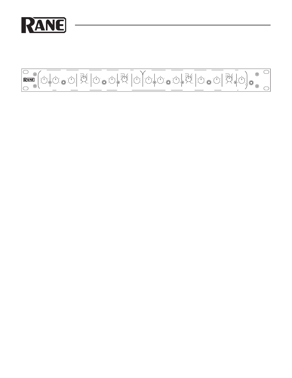
QUICK START
Labels above the controls refer to the unit being operated
in the 2- or 3-Way Stereo mode. Labels below the controls re-
fer to the unit being operated in the 4- or 5-Way Mono mode.
Set the STEREO/MONO switch appropriately. The fact that
the AC 23B is a multiple function unit means the outputs are
switched around in Mono mode.
To operate the unit in Stereo 3-Way mode, be sure the rear
panel switches are set for STEREO 3-WAY. Following the
labels above the controls and jacks in logical order, you will find
Channel 1 Master Input LEVEL, LOW Output, MID Output,
and HIGH Output, with the same for Channel 2. If you need a
summed Mono Low Ouput, see ‘Monoing the Low Outputs’ on
page Manual-7.
To use the unit as a Mono 5-Way, first check that the Chan-
nel 1 and 2 switches are set to 3-WAY, and the other switch is
set to MONO. Connect the INPUT source to Channel 1 only.
Following the labels below the jacks, look at SUB OUT, then
look over at LOW OUT, now go back to MID OUT, then over
to HIGH-MID OUT and then proceed to the HIGH OUT. An
internal switch determines 4 or 5-Way mode. Our apologies to
4-Way users: We must ship the units in the 5-Way mode since
normal Stereo 3-Way operation demands it: a fact not the least
bit obvious, but nevertheless, a fact it remains. Pity. See page
Manual-6 for Mono 4-Way configuration.
In agreement with IEC and AES/ANSI standards, AC 22B
wiring convention is pin 2 Positive, pin 3 Negative (return), pin
1 chassis ground. See the “Sound System Interconnection” Rane-
Note included with this manual for more information on cabling
and grounding requirements.
CAUTION: Never connect anything except an approved
Rane Power supply to the thing that looks like a red tele-
phone jack on the rear of the AC 23B.
This is an 18 VAC center
tapped power input. Consult the Rane factory for a replacement
or substitution.
IMPORTANT NOTE
CHASSIS GROUNDING
If after hooking up your system it exhibits excessive hum or buzzing, there is an incompatibility in the grounding configuration
between units somewhere. Your mission, should you accept it, is to discover how your particular system wants to be grounded. Here
are some things to try:
1. Try combinations of lifting grounds on units that are supplied with ground lift switches or links.
2. If your equipment is in a rack, verify that all chassis are tied to a good earth ground, either through the line cord grounding pin or
the rack screws to another grounded chassis.
3. Units with outboard power supplies do not ground the chassis through the line cord. Make sure that these units are grounded
either to another chassis which is earth grounded, or directly to the grounding screw on an AC outlet cover by means of a wire
connected to a screw on the chassis with a star washer to guarantee proper contact.
4. Try moving the device away from high magnetic field sources, such as large transformers used in power amplifiers.
Please refer to the included RaneNote “Sound System Interconection” for further information on system grounding.