Figure 7. thermistor wiring diagram, Figure 8. manual reset connections, Installation – Metalfab Martin Motomagnetic Electric Vibrator User Manual
Page 16
Martin Engineering M3286-8/01
12
MOTOMAGNETIC
®
Electric Vibrators
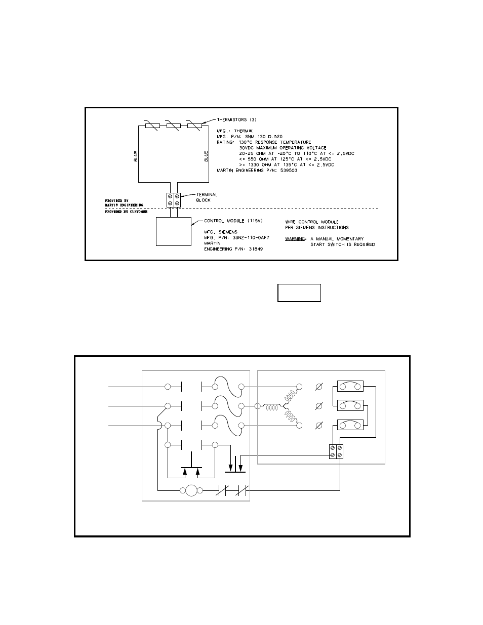
3. For diagrams 5A and 5B, wire thermistor to control module in accordance
with Figure 7. (Martin Engineering recommends using the control
module shown in Figure 7, but other suitable control modules may be
used.)
Figure 7. Thermistor Wiring Diagram
NOTE
The thermostat terminals on CDX units are identified as P1
and P2. The thermostat circuit is rated 600 Vac maximum and
720 VA. A manual momentary start switch must be used.
4. For CDX vibrators, wire thermostats to control circuit. See Figure 8.
Figure 8. Manual Reset Connections
Stop
Start
1
2
3
Motor
Motor
Windings
P1
P2
Starter
Overload
Contacts
Starter
Coil
W
V
U
Motor Starter
Li
n
e
Installation