Figure 3. mounting bolt tightening sequence, Table i. mounting bolts and torque requirements, Installation – Metalfab Martin Motomagnetic Electric Vibrator User Manual
Page 10
Martin Engineering M3286-8/01
6
MOTOMAGNETIC
®
Electric Vibrators
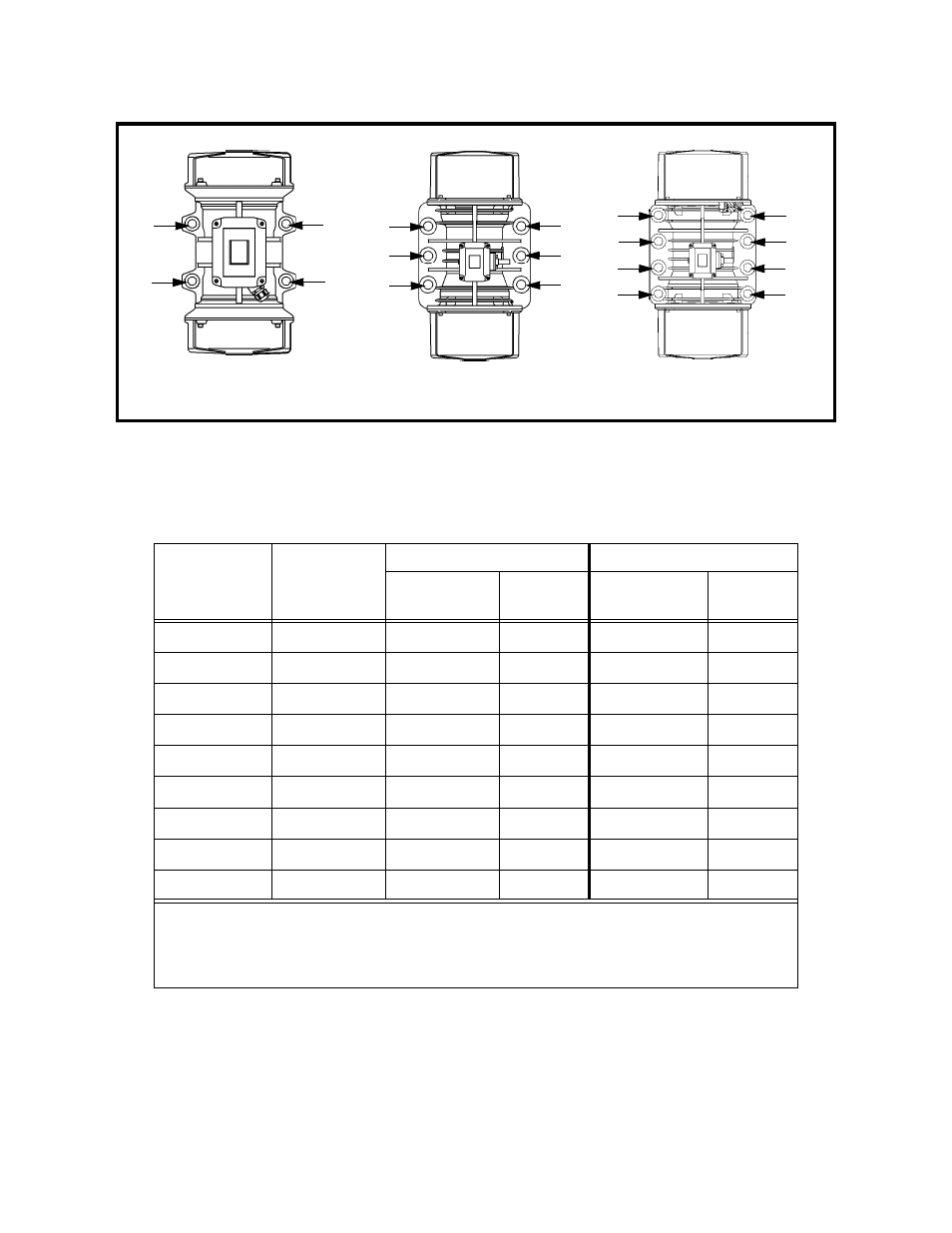
Figure 3. Mounting Bolt Tightening Sequence
7. After the vibrator has been operated for 10 to 20 minutes, check bolt
torque. Tighten if necessary.
Table I. Mounting Bolts and Torque Requirements*
*Torque specifications are for reference only. Contact fastener manufacturer for specific information
regarding bolt torque.
4 Bolts
6 Bolts
8 Bolts
1
3
2
4
1
3
6
2
4
5
1
3
5
7
2
4
6
8
Vibrator Type
Frame Size*
English
Metric
Bolt Size
(Gr 5)
Dry Torque
(ft-lb)
Bolt Size
Dry Torque
(kgm)
CD, CDS
00, 01
5/16 in. -18NC
17
M8
2
CD, CDS
10, 20
1/2 in. -13NC
76
M12
8
CD, CDS, CDX 30, 35, 40, 50
†
5/8 in. -11NC
137
M16
19
CD, CDX
50
††
, 60
3/4 in. -10NC
288
M20
38
CD, CDX
70
7/8 in. -9NC
430
M22
56
CD
80
1 in. -8NC
644
M24
71
CD
90, 95
1 in. -8NC
644
M25
89
CD
97
1-1/2 in. -8NC
1950
M36
190
CD
100, 105, 110
1-3/4 in. -8NC
N/A
M42
**290
*See “Part Numbers” section for specific model numbers.
**Plated bolt with antiseize.
†
Frame size for CD model only.
††
Frame size for CDX model only.
Installation