Figure 5. wiring diagrams, Installation, Diagram 2a – Metalfab Martin Motomagnetic Electric Vibrator User Manual
Page 14: Diagram 2c, Diagram 1a, Diagram 1e, Diagram 5a, Diagram 5b, Cdx model, 6-lead, 3-phase, Cdx model, 9-lead, 3-phase
Martin Engineering M3286-8/01
10
MOTOMAGNETIC
®
Electric Vibrators
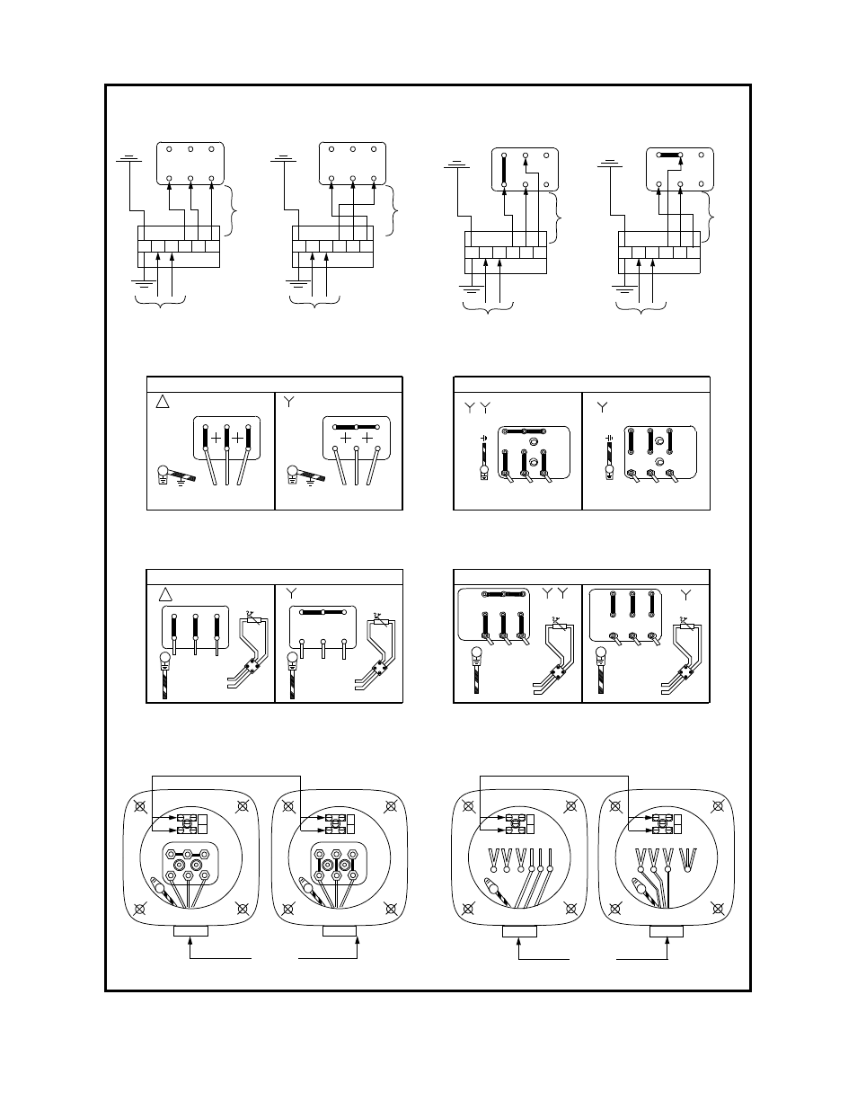
Figure 5. Wiring Diagrams
Low Voltage
High Voltage
3-phase
power supply
Ground
Ground
W2
U2
V2
U1
V1 W1
U1
V1 W1
W2
U2
V2
DIAGRAM 2A
Diagram 2A
Gr
ou
nd
3-phase
power supply
460 V
230 V
1
2
3
4
5
6
7
8
9
1
2
3
4
5
6
7
8
9
DIAGRAM 2C
60 HZ
Diagram 2C
3-phase
power supply
3-phase
power supply
Gr
ou
nd
U1
V1
W1
W2
U2
V2
G L1 L2 T1 T2 T3
Ho
t
Ne
utr
a
l
3-wire cord
115V, 60Hz
power supply
U1
V1
W1
W2
U2
V2
G L1 L2 T1 T2 T3
Ho
t
N
eut
ra
l
3-wire cord
115V, 60Hz
power supply
4-wire
Diagram 1A
Rotation in one direction
Rotation in opposite direction
cord
4-wire
cord
U1
V1
W1
W2
U2
V2
U1
V1
W1
W2
U2
V2
Diagram 1E
G L1 L2 T1 T2 T3
Ho
t
Neu
tra
l
3-wire cord
115V, 60Hz
power supply
G L1 L2 T1 T2 T3
Ho
t
N
eut
ra
l
3-wire cord
115V, 60Hz
power supply
4-wire
Rotation in one direction
Rotation in opposite direction
cord
4-wire
cord
Diagram 5A
Low Voltage
High Voltage
3-phase
power supply
Gr
ou
nd
W2
U2
V2
U1
V1
W1
W2
U2
V2
DIAGRAM 5A
To control
module
Thermistor
U1
V1
W1
Gr
ou
nd
3-phase
power supply
To control
module
Thermistor
60 HZ
3-phase
power supply
3-phase
power supply
Gr
ou
nd
DIAGRAM 5B
To control
module
Thermistor
Gr
ou
nd
To control
module
1
2
3
4
5
6
7
8
9
230 V
1
2
3
4
5
6
7
8
9
Thermistor
460 V
Diagram 5B
P1
P2
W2
U2
V2
U1
V1
W1
P1
P2
W2
U2
V2
U1
V1
W1
Cable Entry
Y - High Voltage
s
- Low Voltage
Thermostat Connection Diagram to Terminal Board
G
G
CDX Model, 6-lead, 3-phase
4 7 5 8 6 9 1 2 3
U V
W
4
7
5
8
6
9
1
2
3
U
V
W
Cable Entry
Y (S) - High Voltage
YY - Low Voltage
9700 K Thermostat Connection Diagram to Terminal Board
G
G
P1
P
2
P1
P2
CDX Model, 9-lead, 3-phase
switch
bo
x
switch
bo
x
sw
it
c
h
bo
x
switch
bo
x
Installation