Assembly instructions 4/5, Step 5 step 6, Step 7 – Home Styles 4528-95 User Manual
Page 4: Op q q p
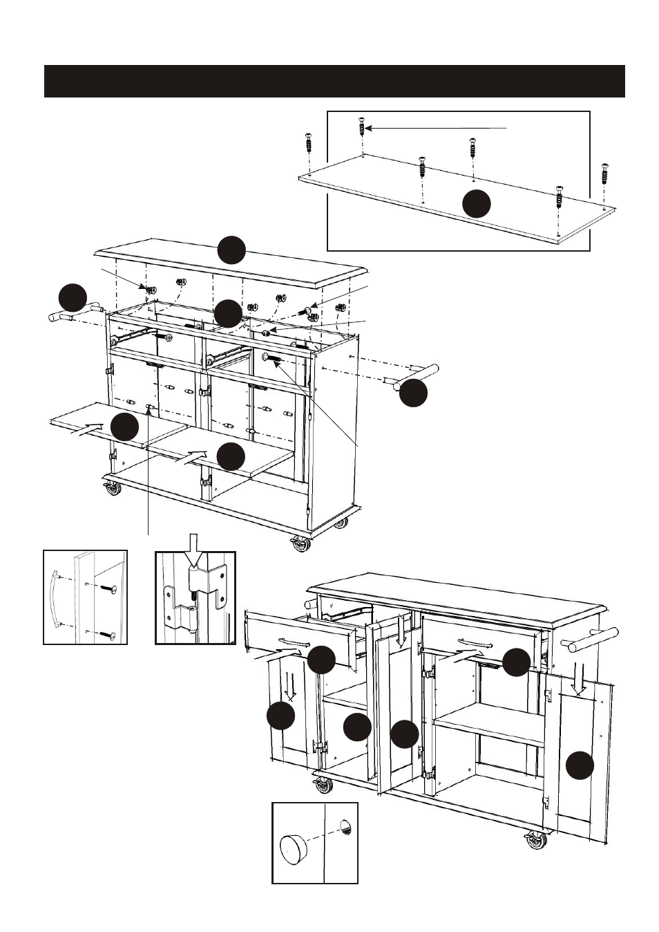
Put Cam Lock Screws into the
pre-drilled holes in Top (A).
STEP 5
STEP 6
Assembly Instructions 4/5
Cam Lock Screw
Cam Lock
Head Cap Bolt
Head Cap Bolt
(long)
Cross Dowel
A
A
K
M
M
N
N
Adjustable Pin
Insert Adjustable Pins into
the side panels and middle
panel at the desired level.
Place Shelves (N) into position.
Attach Side Bar (M) to the unit
with Head Cap Bolts.
Insert the Cross Dowel into
the hole of Divider (K) and
tighten Head Cap Bolt (long)
from the back of unit.
Place Top (A) onto the unit,
using Cam Locks.
Figure 2
Figure 1
STEP 7
Attach Pull Handles to the
Doors (O) and (P) using Machine
Screws. (See figure 1)
Attach the Doors (O) and (P) to
the side panels and middle panel
slide the door lift hinges into the
side panel and middle panel
lift hinges. (See figure 2)
Slide the Drawers (Q) into place.
Cover up all holes with
Wood Plug. (See figure 3)
Figure 3
O
O
P
Q
Q
P
- 9200-1611 (5 pages)
- 9200-1411 (5 pages)
- 9200-1211 (5 pages)
- 9200-1111 (5 pages)
- 9100-1711 (5 pages)
- 9100-1611 (5 pages)
- 9100-1411 (5 pages)
- 9100-1211 (5 pages)
- 9100-1111 (5 pages)
- 9001-0711 (5 pages)
- 9001-0611 (5 pages)
- 9001-0411 (5 pages)
- 9001-0211 (5 pages)
- 9001-0111 (5 pages)
- 5257-95 (5 pages)
- 5254-95 (5 pages)
- 5252-95 (5 pages)
- 4508-95 (5 pages)
- 5520-958 (2 pages)
- 5061-95 (4 pages)
- 5134-95 (4 pages)
- 5411-61 (3 pages)
- 5411-615 (3 pages)
- 5033-958 (2 pages)
- 5033-94 (2 pages)
- 5033-94 (6 pages)
- 5010-948 (7 pages)
- 9100-1077G (5 pages)
- 9100-1066G (5 pages)
- 9100-1071 (4 pages)
- 9100-1027G (5 pages)
- 9100-1072 (4 pages)
- 9100-1023 (4 pages)
- 9001-0066G (5 pages)
- 9001-0047G (6 pages)
- 5588-948 (2 pages)
- 5588-948 (9 pages)
- 5543-948 (2 pages)
- 5543-948 (9 pages)
- 5542-948 (9 pages)
- 5542-948 (2 pages)
- 5181-64 (5 pages)
- 5180-64 (5 pages)
- 5033-358 (1 page)
- 5020-65 (6 pages)