Assembly instructions 2/5, Step 1, Step 2 – Home Styles 4528-95 User Manual
Page 2
Assembly Instructions 2/5
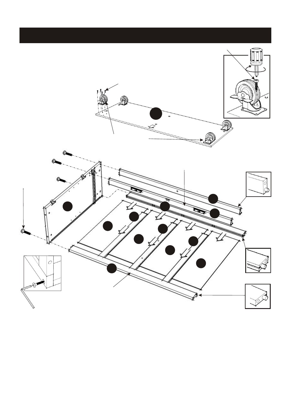
STEP 1
IMPORTANT
Do not tighten up all the screws until each part is properly assembled.
You should keep Hex Wrench in a safe place as you may need to
tighten up the Head Cap Bolts in the future.
L
Attach the two locking Casters
to the front of the Base (L).
Attach the two non-locking
casters to the back of the
Base (L). (See figure 1)
(Note : The ‘Arrow’ sticker
indicates the front of the base.)
Head Cap Bolt
Wood Screw
Wood Screw
Locking Caster
(Figure 1)
B
H
H
H
H
F
E
E
J
G
G
I
STEP 2
Attach Back Stretcher (E) to Side Panel (B) at the lower position with Head Cap Bolt.
Attach Back Pieces (F) and (G) to the Back Stretcher (E), then slide Back Panels (H) in place.
Attach Back Stretcher (E) to the unit at upper position.
Tighten the Head Cap Bolt.
Attach Front Pieces (I) and (J) to the unit with Head Cap Bolts.
Lower Position
Upper Position
Tighten Head
Cap Bolt by
Hex Wrench.
- 9200-1611 (5 pages)
- 9200-1411 (5 pages)
- 9200-1211 (5 pages)
- 9200-1111 (5 pages)
- 9100-1711 (5 pages)
- 9100-1611 (5 pages)
- 9100-1411 (5 pages)
- 9100-1211 (5 pages)
- 9100-1111 (5 pages)
- 9001-0711 (5 pages)
- 9001-0611 (5 pages)
- 9001-0411 (5 pages)
- 9001-0211 (5 pages)
- 9001-0111 (5 pages)
- 5257-95 (5 pages)
- 5254-95 (5 pages)
- 5252-95 (5 pages)
- 4508-95 (5 pages)
- 5520-958 (2 pages)
- 5061-95 (4 pages)
- 5134-95 (4 pages)
- 5411-61 (3 pages)
- 5411-615 (3 pages)
- 5033-958 (2 pages)
- 5033-94 (2 pages)
- 5033-94 (6 pages)
- 5010-948 (7 pages)
- 9100-1077G (5 pages)
- 9100-1066G (5 pages)
- 9100-1071 (4 pages)
- 9100-1027G (5 pages)
- 9100-1072 (4 pages)
- 9100-1023 (4 pages)
- 9001-0066G (5 pages)
- 9001-0047G (6 pages)
- 5588-948 (2 pages)
- 5588-948 (9 pages)
- 5543-948 (2 pages)
- 5543-948 (9 pages)
- 5542-948 (9 pages)
- 5542-948 (2 pages)
- 5181-64 (5 pages)
- 5180-64 (5 pages)
- 5033-358 (1 page)
- 5020-65 (6 pages)