Installation, Gas supply line, Gas connection – B&C Technologies IP Series Commercial Ironer User Manual
Page 15: Gas supply connection requirements
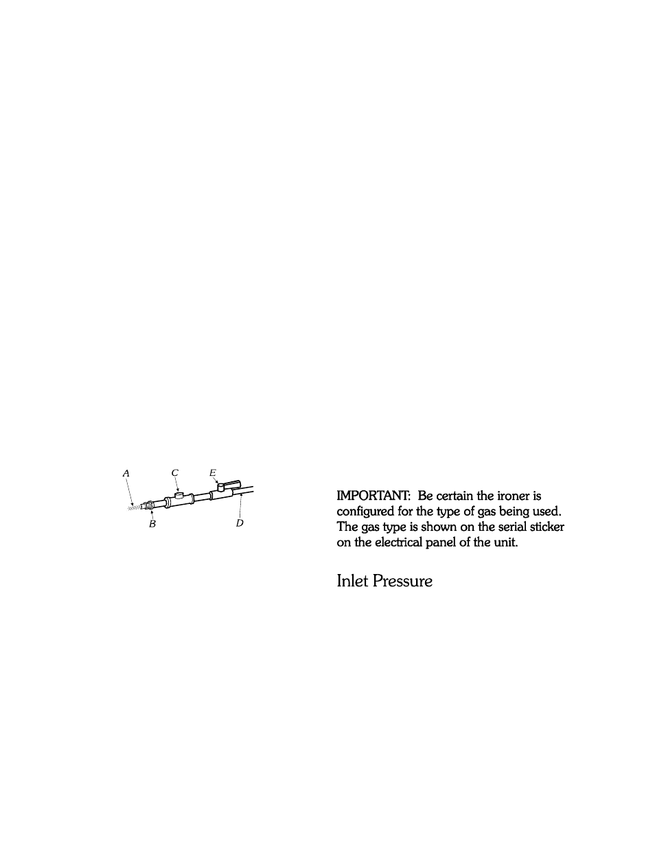
A. ½” flexible gas connector
B. ¾” pipe to flare adapter fitting
C. 1/8” NPT plugged tapping
D.
¾” NPT gas supply line
E. Gas shutoff valve
Gas Supply Line
!
!
!
!
¾" IPS pipe is recommended.
¾” approved tubing is acceptable for
lengths under 25 ft (6.1 m) if local codes
and gas supplier permit.
Must include 1/8 NPT minimum plugged
tapping accessible for test gauge
connection, immediately upstream of the
gas connection to the dryer (see
illustration).
Must include a shutoff valve:
An individual manual shutoff valve must
be installed within 6 feet (1.8m) of the
equipment in accordance with the
National Fuel Gas Code, ANSI Z223.1.
The location should be easy to reach for
opening and closing.
”
Installation
Gas Connection
15
Gas Supply Connection
Requirements
There are many methods by which the IP
series Ironer can be connected to the gas
supply. Following are some guidelines for
methods of connection.
Flexible stainless steel gas connector:
Option 1:
If local codes permit, use a new flexible
stainless steel connector (Design certified by
the American Gas Association or CSA
International) to connect between the ironer
and the gas supply line. Use an elbow and
a ½” flare x ¾” NPT adapter fitting
between the stainless steel gas connector
and the gas inlet of the machine as needed
to prevent kinking.
Other approved piping:
Lengths under 25 feet (6.1m) use ¾”
approved tubing.
Lengths over 25 feet (6.1m) should use
larger piping.
Pipe joint compounds that resist the action
of gas must be used. DO NOT USE
TEFLON®/PTFE TAPE.
Use a manometer to verify that the inlet
pressure meets the following requirements:
Natural Gas service must be supplied at 4-
14 inches of water column pressure.
LP Gas service must be supplied at 11-14
inches of water column pressure.
Option 2
!
!
!