Tjernlund SS1 SideShot (Discontinued Version - Pre UC1 Universal Control) 8504041 Rev A 11/99 User Manual
Page 16
15
4. Connect terminal R of the SideShot terminal strip to the
TR(COM) terminal of the 24V gas valve. NOTE: Do not
remove the factory installed wire from the TR(COM) terminal.
5. Connect terminal L1 of the SideShot terminal strip to L1.
6. Connect terminal L2 of the SideShot terminal strip to L2.
7. Connect the Ground to grounding screw in SideShot electrical box.
1. Remove the wire that is factory installed to the TH (HOT) terminal
of the 24V gas valve.
2. Connect the wire removed from the TH(HOT) terminal in step 1 to
terminal O of the SideShot terminal strip.
3. Connect terminal Y of the SideShot terminal strip to the TH (HOT)
terminal of the 24V gas valve.
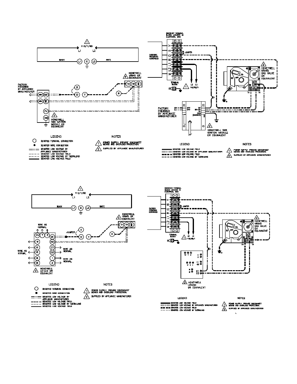
LADDER DIAGRAM
SIDESHOT CONNECTED TO A 24V BOILER WITH A STANDING PILOT
NOTES: The SideShot is always interlocked with the gas valve of the appliance. Wire all other furnace/boiler controls as normally
done when conventional venting before continuing. Disconnect power from the appliance before attempting to interlock the SideShot.
LADDER DIAGRAM
SIDESHOT CONNECTED TO A 24V FURNACE OR BOILER WITH INTERMITTENT IGNITION
CONNECTION DIAGRAM
CONNECTION DIAGRAM
- 950-0014 Relay Timer Airotronics Non-Adjustable 8504067 Rev. A 11/11 (2 pages)
- 950-0014 Relay-Timer (Old Style) Kit Non-Adjustable 8504067 Rev. 10/97 (2 pages)
- 950-0015 SS2 Motor Kit 8504069 Rev. 05/98 (2 pages)
- 950-0017 SS2 Impeller Kit 8504070 Rev. 03/98 (1 page)
- 950-0019 SS2 Venter Housing Kit 8504072 Rev. 05/98 (1 page)
- 950-4020 I, IL, XL Motor Kit 8504051 Rev 2 11/96 (2 pages)
- 950-0452 PAI-1,2 Prover Kit 8504044 Rev. 1 04/97 (2 pages)
- 950-0453 PAI-T Timer-Clock Kit 8504045 Rev. 1 05/97 (2 pages)
- 950-0476 Commercial PAI Series Fan Prover Kit 8504086 Rev. A 01/00 (1 page)
- 950-0484 Mac-3 (Discontinued - No longer available) Board Kit 8505009 Rev. 08/00 (9 pages)
- 950-0625 SS1 Motor Kit 8504016 Rev. A 11/99 (2 pages)
- 950-0640 SS1 Series High Limit Kit 8504042 Rev. 2 03/98 (1 page)
- 950-0740 SS1C Series High Limit Kit 8504042 Rev. 2 03/98 (1 page)
- 950-0750 SS1C Fan Prover Kit 8504037 Rev. 09/94 (1 page)
- 950-1007 Fan Prover Kit 8504113 (1 page)
- 950-1020 Motor Kit 8504048 Rev 2 12/97 (2 pages)
- 950-1021 Motor Kit 8504049 Rev 2 11/96 (2 pages)
- 950-1022 Motor Kit 8504050 Rev. 1 11/96 (2 pages)
- 950-1040 24V Relay Kit 8504052 Rev. 3 10/97 (2 pages)
- 950-1067 Relay-Timer Airotronics - Adjustable 8504053 Rev. A 04/12 (4 pages)
- 950-1067 Relay-Timer (Old Style) Kit 8504053 Rev 4 09/96 (4 pages)
- 950-2043 ND-1 Post Purge Burner Kit 8504004 Rev 0196 (4 pages)
- 950-2061 Pilot Saver Kit 8504028 Rev 2 09/95 (2 pages)
- 950-2064 L-185 Safety Interlock Kit 8504020 Rev 3 09/96 (2 pages)
- 950-2080 New Style Gas Pressure Switch (1 page)
- 950-2420 24SP200 Spillage Kit 8504056 Rev 1 03/97 (2 pages)
- 950-3022 Motor Kit 8504066 Rev 1 05/98 (3 pages)
- 950-4030 AD-1 Speed Controller Kit 8504005 Rev 03/96 (1 page)
- 950-8804 UC1 Universal Control Board Kit (Version X.06) 8505017 Rev D 07/05 (17 pages)
- 950-8804 UC1 Universal Control Board Kit (Version X.04) 8505017 Rev A 05/03 (16 pages)
- SB1 Heat Shield Kit 8504184 (2 pages)
- DJ-3, D-3, HD, I, IL, XL Draft Inducer 8504003 Rev A 07/00 (12 pages)
- PS1505 Fan Prover 8504008 Rev 1 01/97 (2 pages)
- AD-1 for Wood or Coal Stoves 8504012 Rev A 10/99 (2 pages)
- CSA1 Chimney Stack Assist Kit 8504201 (8 pages)
- RTS8 Rooftop Mounting Kits 8504161 (1 page)
- COP2 Constant Operating Pressure Exhaust Control 8504208 (11 pages)
- CIC1 Heater Interlock Control for COP2 8504209 (2 pages)
- DCOP1 Constant Operating Pressure Draft Control 8504174 (Discontinued) (20 pages)
- XCOP1 Constant Operating Pressure Exhaust Control 8504175 (Discontinued) (7 pages)
- UCRT Rooftop Inducer Universal Control (Version X.06) 8504162 Rev A 05/11 (16 pages)
- UCRT Rooftop Inducer Universal Control (Version X.06) 8504162 Rev 01/10 (16 pages)
- MAC1E Control Version F (Compatible with UC1 Control) 8504110 Rev B 11/05 (2 pages)
- MAC1E Control (Compatible with UC1 Control) 8504110 Rev A 12/04 (2 pages)
- MAC4E Control Version F (Compatible with UC1 Control) 8504112 Rev B 08/05 (2 pages)