0 installation, 1 unpacking and assembly, 2 mounting the iqube and remote display – Rice Lake Tracer AVi - v1.0 User Manual
Page 6: 3 cable connections, 4 load cells, Installation, J2 j3, J7 j5
2
Tracer AVi
Installation Manual
2.0
Installation
This section describes procedures for connecting load
cell, power, and serial communications cables to the
iQube
TM
enclosure.
Drawings and replacement parts
lists are included for the service technician.
Use a wrist strap to ground yourself and
protect components from electrostatic
discharge (ESD) when working inside the
iQube
enclosure.
Disconnect AC power from the main module before installing
remote displays.
2.1
Unpacking and Assembly
Immediately after unpacking, visually inspect the
contents to ensure all components are included and
undamaged. The shipping carton should contain the
i Q u b e
, t h e r e m o t e d i s p l a y, t h i s m a n u a l , a n d
connection cables. If any parts were damaged in
shipment, notify Rice Lake Weighing Systems and the
shipper immediately.
See Table 2-4 on page 4 for the
iQube
cables.
2.2
Mounting the iQube and Remote
Display
The
iQube
and remote display are two separate
components. The main board is installed in the
iQube
.
All components can be installed in separate locations.
The
iQube
can be placed either upright or on its side.
Mounting hardware is not included in the parts kit.
2.3
Cable Connections
The single channel
iQube
provides one load cell
connector, two remote display connectors, one host
(PC) com port connector for connecting to the PC
running
VIRTUi
, and an AC power cord.
2.4
Load Cells
The load cell wired to connector J3 in the
iQube
, is
assigned a default name A1. J3 is wired to a DB-9 on
the enclosure panel.
.
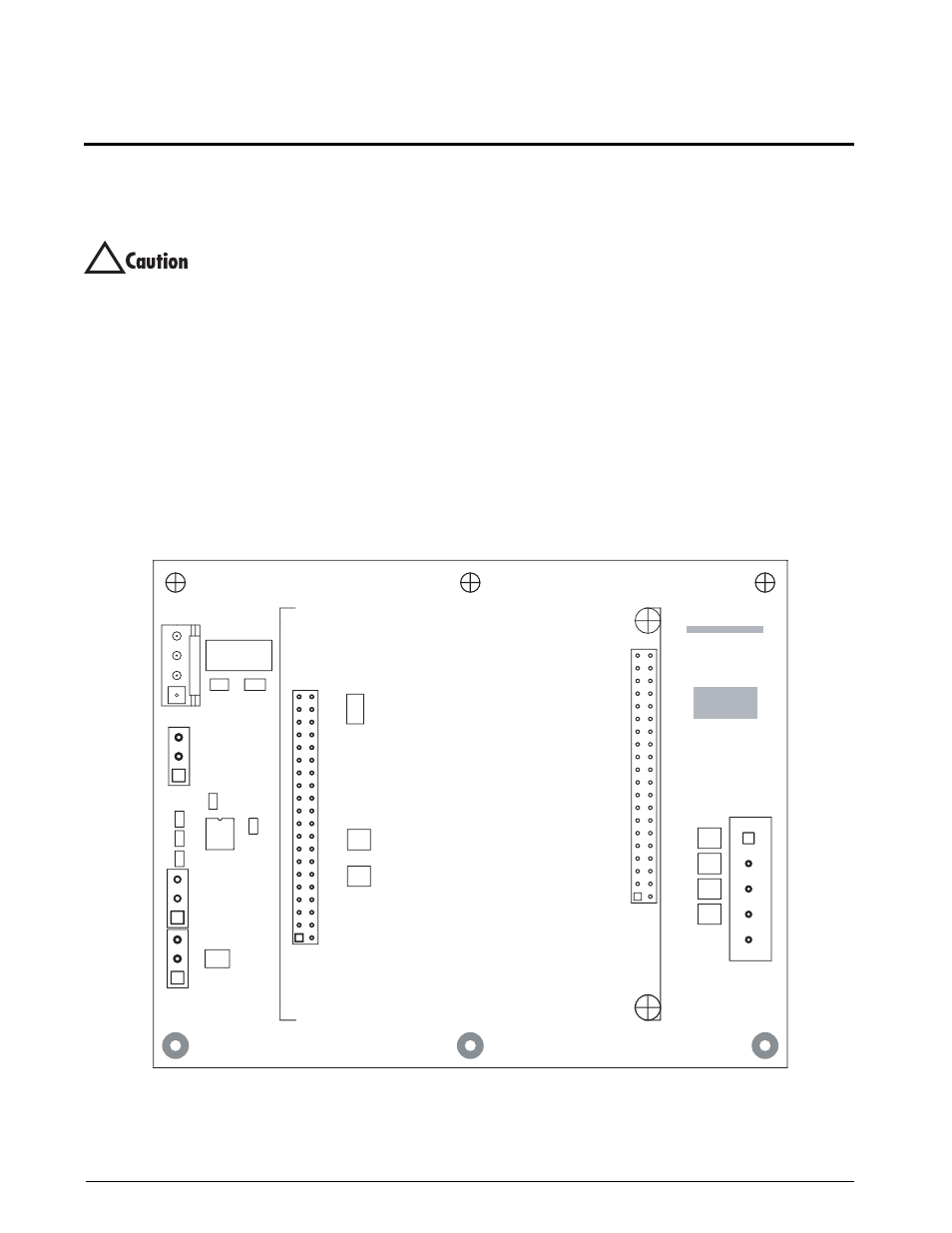
Figure 2-1.
iQube Connector Board with Core Module
!
GND
TxD
DC+
TxD
RxD
1
DC IN
1
DC+
GND
TxD
GND
G2E
1
REMOTE
1
–EXC
+
S
IG
Rev.
P/N
REMOTE
HO
S
T
S
ERIAL
1
–
S
IG
+EXC
Assembly
RICE LAKE
S
HLD
C
3
R1
C4
R2
D1
C2
C5
J4
C1
J1
J6
TVS6
TVS5
C6
J7
J5
J2
J3
TVS1
TVS4
U1
TVS3
TVS2
F1