420 plus enclosure reassembly, 420he enclosure reassembly, Analog output calibration – Rice Lake SURVIVOR 420 Plus/420HE Analog Output Card Installation User Manual
Page 2: Enter setup mode and go to the, Menu (see figure 4). • set
2
420 Plus/420HE
Analog Output Card Installation Instructions
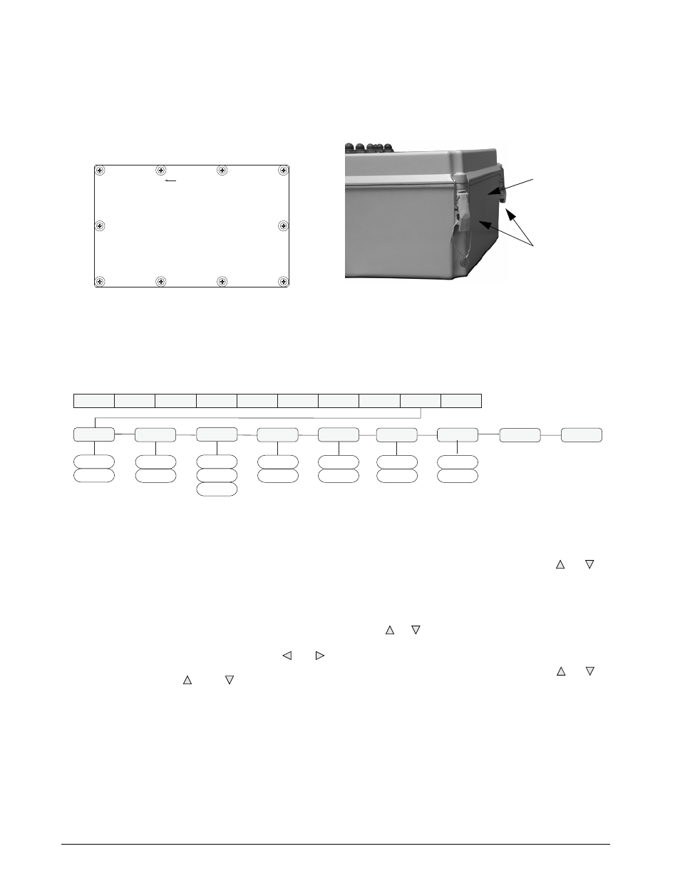
420 Plus Enclosure Reassembly
Once cabling is complete, position the backplate over
the enclosure and reinstall the backplate screws. Use
the torque pattern shown in Figure 2 to prevent
distorting the backplate gasket. Torque screws to 15
in-lb (1.7 N-m).
Figure 2.
420 Plus Backplate Torque Pattern
420HE Enclosure Reassembly
Once cabling is complete, close the front cover of the
indicator and hook the draw latches.
Figure 3.
420HE Enclosure Assembly
Analog Output Calibration
The following calibration procedure requires a multimeter to measure voltage or current output from the analog
output module. No test weights are required for calibration.
NOTE:
The analog output must be calibrated after the indicator itself has been configured and calibrated.
Figure 4. Analog Output Menu
1. Enter setup mode and go to the
ALGOUT
menu
(see Figure 4).
•
Set
OFFSET
to 0% for 0–10 V output, 20%
for 4–20 mA output
•
Set
MIN
to lowest weight value to be
tracked by the analog output
•
Set
MAX
to highest weight value to be
tracked by the analog output
To enter
MIN
and
MAX
values, use the and
keys to select the digit; use the numeric
keypad or the and to increment or
decrement the value.
2. Connect multimeter to analog output:
•
For voltage output, connect voltmeter
leads to pins three and four
•
For current output, connect ammeter
leads to pins one and two
3. Adjust zero calibration: Scroll to the
TWZERO
parameter. Check voltage or current reading
on multimeter. Press and hold or to
adjust the zero value up or down.
4. Adjust span calibration: Scroll to the
TWSPAN parameter. Ch eck voltag e or
current reading on multimeter. Press and hold
or to adjust the span value up or down.
5. Final zero calibration: Return to the
TWZERO
parameter and verify that the zero calibration
has not drifted. Press and hold or to
re-adjust the zero value as required.
6. Return to normal mode. Analog output
function can be verified using test weights.
1
6
9
4
2
5
7
10
Torque Pattern
8
3
D r a w
Latches
Top of
Indicator
XXXXXXX
XXXXXXX
ALGOUT
DIGIN
SETPNT
XXXXXXX
PROGRM
PFORMT
SERIAL
CALIBR
XXXXXXX
CONFIG
FORMAT
SOURCE
GROSS
0%
20%
OFFSET
ERRACT
FULLSC
HOLD
000000
number
MIN
10000
number
MAX
TWZERO
NET
TWSPAN
ZEROSC
VERS
MINNEG
OFF
ON
MAXNEG
OFF
ON