Rice Lake SURVIVOR 420 Plus/420HE Analog Output Card Installation User Manual
Analog output card installation instructions, 420 plus enclosure disassembly, 420he enclosure disassembly
November 2010 PN 85455
420 Plus HMI/420HE Digital Weight Indicator
Analog Output Card Installation Instructions
PN 85659
420 Plus Enclosure Disassembly
Ensure power to the indicator is disconnected, then
place the indicator face-down on an antistatic work
mat. Remove the screws that hold the backplate to the
enclosure body. Lift the backplate away from the
enclosure and set it aside.
420HE Enclosure Disassembly
Ensure power to the indicator is disconnected, then
place the indicator on an antistatic work mat. Unhook
the draw latches and open the indicator.
Use a wrist strap to ground yourself and
protect components from electrostatic
discharge (ESD) when working inside
the indicator enclosure.
NOTE:
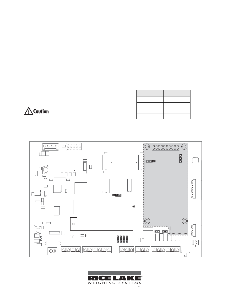
Ensure jumpers JP1 and JP2 are in position 2
(POS2) on the analog output board as shown in
Figure 1.
Mount the analog output module on its standoffs in
the location shown in Figure 1 and plug the module
input into connector J9 on the CPU board. Connect
output cable to the analog output module as shown in
Table 1, then reassemble the enclosure.
Table 1. Analog Output Module J1 Pin Assignments
Figure 1. Analog Output Module Installation on CPU Board
Pin
Signal
1
+ Current Out
2
– Current Out
3
+ Voltage Out
4
– Voltage Out
C7
RESET
R2
C15
C20
C19
R5
MECCA
C3
+5A V
R1
C13
R16
LED2
GND
GD1
C1
F1
DI
2
DI
1
DFB2
TR1
TVS2
TVS3
TVS6
C33
C31
DO2 DO1
C10
C9
+5V
G2E
R25
C30
VR3
R6
C8
U7
C5
C6
U8
R15
U1
LED1
EDP/
RS-232
JP2
C65
U3
SW1
SETUP
C32
C2
XT1
DFB1
TR2
TVS1
TVS5
TVS4
+3. 3
R7
R4
C16
C4
DIGIN
1
J1
LOAD CELL
U2
D1
U19
U6
U9
SERIAL
1
9
1
1
2
8
1
1
Gn
d
20mA+
Gnd
TxD
Gnd
Gn
d
DI
2
EXC-
19
20
E XC+
SEN-
SEN+
SIG-
1
5
1
1
1
20mA-
RxD
RxD
TxD
DI
1
SIG+
Micr o-
pr ocesso
r
DISPLA
Y
DRIVERS
KEYPAD
CONNECTOR
ANALOG
OUTPUT
OPTION CARD
REMOTE
SETUP
SWITCH
DC INPUT
R9 R10
R11 R12
ANA
ME
M
AD
HB
J9
J10
U4
OFF TEST
A/D CONVERTER
U10
U11
J2
J3
J4
J7
J8
J11
J12
JP1
J1
4
3
2
1
JP2
POS
1
POS
2
JP 1
POS
1
POS
2
DIGOUT
1
+5V
DO2
Gnd
DO1
J6
R46
R47
U14
JMP3
(Factory Only)
ON
OF F
KEYPAD
CONNECTOR
HE_J2
1
2
B1
+
To be the best by every measure